Technical specifications
8.3 Pin assignment of the serial interface
TIM 1531 IRC
296 Operating Instructions, 02/2018, C79000-G8976-C468-02
Pin assignment of the serial interface
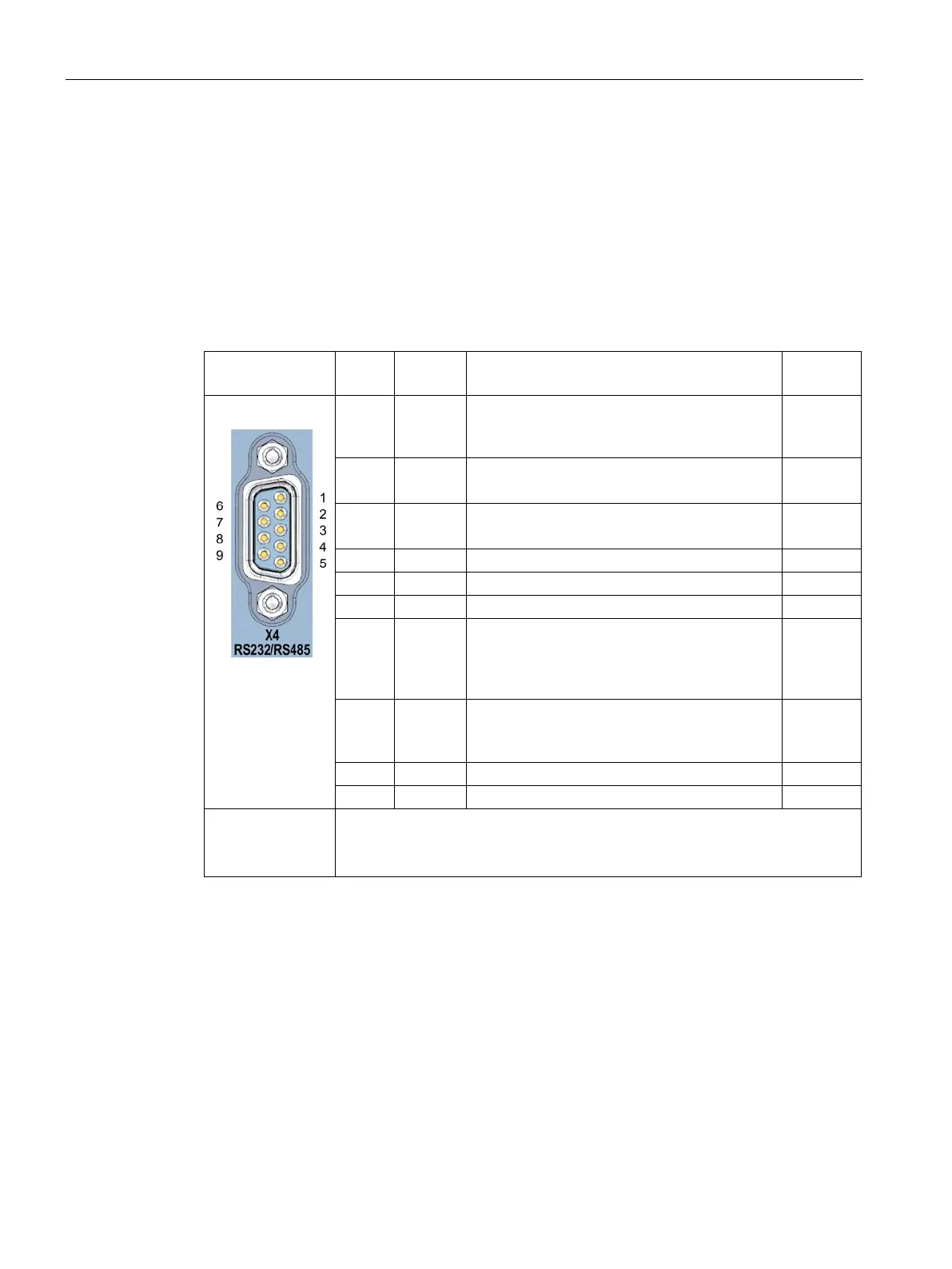
Pin assignment of the serial interface X4 (RS-232 / RS-485)
The table below shows the pin assignment of the 9-pin D-sub miniature plug of the serial
interface. The interface corresponds to the connector assignment of a standardized PC
connector.
Table 8- 2 Pinout of the plug of the serial interface
1 DCD Received signal level
The DCE reports the input of data to be sent to
the DTE (connection establishment).
1
2
Input
2 RxD Received data (DCE → DTE)
Switchover to RS-485 by configuration
3
Input
3 TxD Send data (DTE → DCE)
Switchover to RS-485 by configuration
3
Output
DTE signals readiness to sent to DCE.
Reference mass of the interface
DCE reports readiness for operation to DTE.
7 RTS Turn on transmitter
The DTE requests the DCE to send data on the
data cable. The DTE waits for confirmation of
the readiness to to send (CTS) of the DCE.
Output
8 CTS Ready to send
The DCE can transfer the data coming from the
Input
;
1
DCE = data communication equipment (connected modem)
;
2
DTE = data terminal equipment (TIM / CP)
3
Fore the switchover RS-232 ↔ RS-485 see section .
 Loading...