LEDs, connectors, switches, card slot
2.3 Electrical connectors
TIM 1531 IRC
Operating Instructions, 02/2018, C79000-G8976-C468-02
33
●
For the LED pattern see section Startup - LED pattern (Page 49).
●
For the LED pattern see section Update firmware (Page 284).
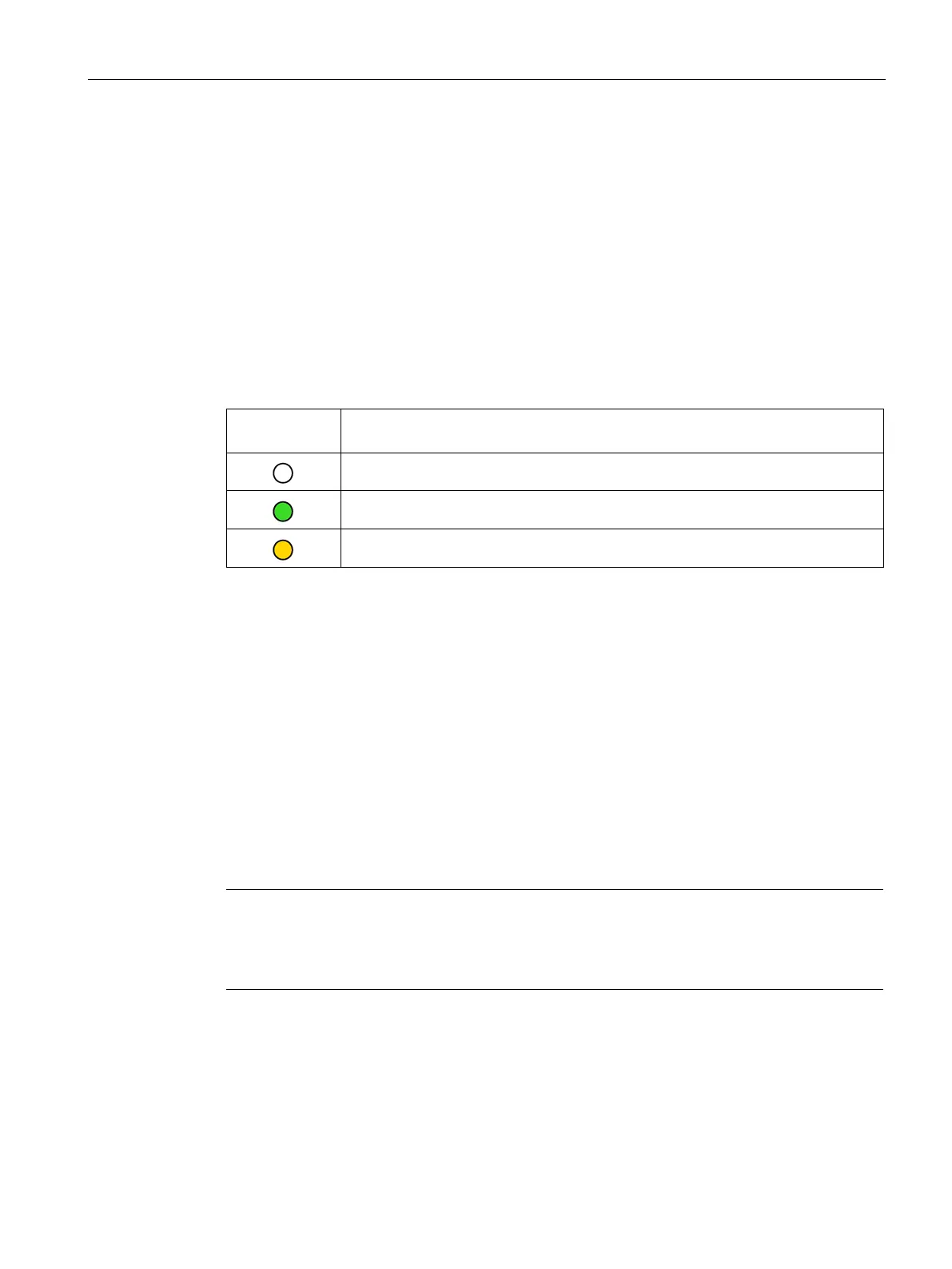
LEDs of the Ethernet interfaces
Every interface has an LED that informs about the connection status with Ethernet and the
message traffic of the port.
Table 2- 4 Meaning of the LED statuses
X1 / X2 / X3
(yellow/green)
No connection to the Ethernet network
Ethernet connection without data transfer
Ethernet connection with data transfer
Electrical connectors
2.3.1
Ethernet interfaces (X1, X2, X3)
Ethernet interfaces
The Ethernet connectors are located behind the cover of the enclosure. The interfaces are
RJ-45 jacks according to IEEE 802.3.
Note
Connection to subnets
The three Ethernet interfaces are not designed as a switch, but are intended for connection
to different networks. Operation
in the same physical network is not permitted.
The pin assignment of the Ethernet interfaces and other data can be found in the section
Technical specifications (Page 293).
 Loading...