111
SJ12 E, SJ16 E, SJ20 E
241914ACA
Pin Charts Section 5 – Procedures
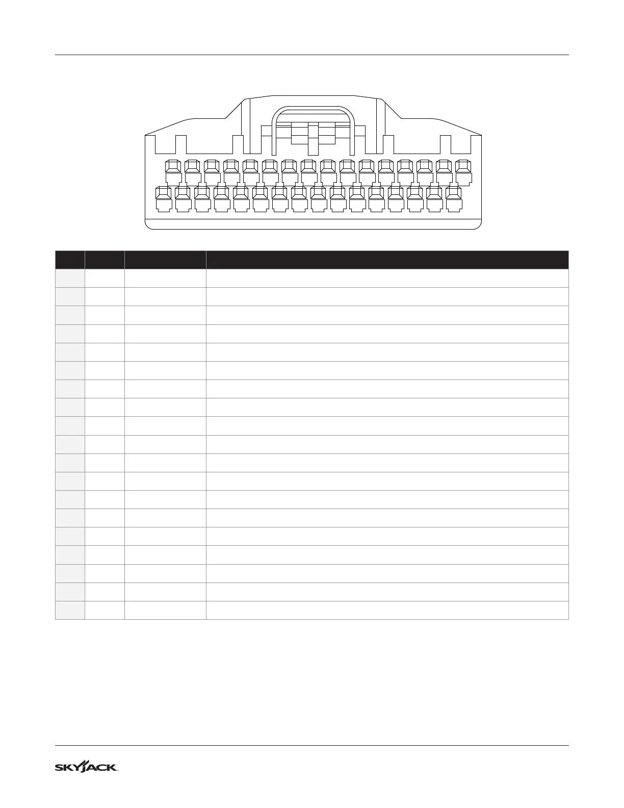
5.6-2 Joystick 32-Pin Connector Chart
Plug Pin # Wire # and Color Wire Function
P1-6 Not used
P7 12 Brown/Red 24V Input from S3 Lift/Off/Drive switch for Drive Select
P8 49 Green 24V Input from S8 Horn
P9-14 Not used
P15 60 Black/Red/Green 24V reference Output (pulsed) for PL-1 Power On LED of S4 Emergency Stop switch
P16 08C Purple/White 24V Input B+ from S10 Key switch in Platform mode select
P17 08 Purple/White 24V Input B+ from S4 Emergency Stop switch for power on
P18 51 Black/Green 24V Input from LS3 Limit switch for Deck in Service position (OFF when Extended)
P19-21 Not used
P22 120 Black 24V Input from S7 Indoor/Outdoor switch option (ON when Outdoor mode)
P23 09 Orange 24V Input from S3 Lift/Off/Drive switch for Lift Select
P24 12A Grey/Orange 24V Input from LS4 Limit switch for Deck Extended (OFF when Extended)
P25 82A Brown/White 12V Output for Load Cell supply
P26 CanL Green Communication CanL
P27 CanH Yellow Communication CanH
P28-29 Not used
P30 120A Black Spare (Not used)
P32 00 White 0V reference Ground B-
Enable Trigger, Steer Left, and Steer Right are done with BIT functions (byte 1)