III-149
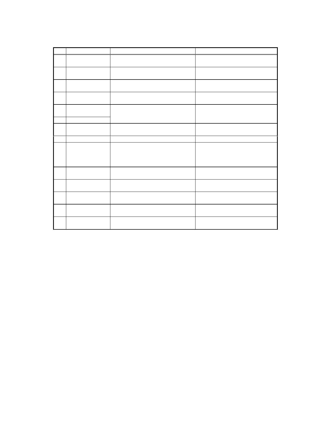
Table 3-12 Descriptions of SELF MONITOR items
For displaying the connection
status of the SR.
“CONNECTION” or
“DISCONNECTION”
For displaying the connection
status of the power supply.
For displaying the frequency of
the transducer installed.
For displaying whether the
transmission is overloaded.
“DISCONNECTION” or
“ERROR” or “CONNECTION”
Not in use for 38, 70,120kHz.
For displaying the A/D status.
“DISCONNECTION” or
“ERROR” or “CONNECTION”
Not in use for this system.
Not in use for this system.
For displaying the status of the
phase circuit board
“DISCONNECTION” or
“ERROR” or “HIGH
PRECISION” or ”LOW
PRECISION”
The offset value of the X-axis of
the phase.
The offset value of the Y-axis of
the phase.
The count number of connections
made to SR.
For displaying the version of the
CPU.
For displaying the version of the
FPGA.
* “CONNECTION” is displayed in green, and “ERROR” is in red.
* ”PHASE STATUS”,”X PHASE OFFSET” and ”PHASE OFFSET” is not use
in 15, 24,50,75,200kHz.