V-1
5-2 Hardware problems: examples and
measures
This chapter describes problems that may occur before checking by the self-
monitor described in Section 3-1-6-2.
The power key fails to turn red.
(1) Check that the power cable of PRC-63 Type Computing Unit
is connected.
(2) Check that the connection to the RC connector of PRC-63
Type Computing Unit is not loose.
Although power is ON, no picture is
displayed.
(1) If the power lamp of the indicator is red, the RGB cable
may not be connected, or PRC-63 Type Computing Unit
may not be activated.
(2) Check whether the RGB cable is correctly connected to
the indicator and PRC-63 Type Computing Unit.
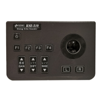
(3) Check that the power key of RC-21 Type Controller is
turned ON in green color to make sure PRC-63 Type
Computing Unit is activated.
(4) If the power key of RC-21 Type Controller is red, press the
power key to turn ON.
(5) If the power key is not red, refer to the measures described
in the above [RC-21 Type Controller].
(6) Check whether the values of brightness and contrast are
too low.
(7) Check whether the fuse of the indicator is blown.
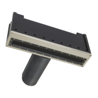
[PRC-63 Type Computing Unit]
Although the power key of RC-21
Type Controller is ON in green,
no power is supplied.
(1) Turn the power key of the RC-21 Type Controller ON again.
(2) SR-87 Type Transceiver may not be activated. Referring to
[SR-87 Type Transceiver] on the next page, activate SR-87
Type Transceiver.
(3) When the battery inside the model PRC-63 runs down, the
system can no longer start. In such a case, contact your
local dealer or our serviceman to have the battery replaced.
When the measurement icon is
activated, “SR
COMMUNICATION ERROR
CHECK CONNECTION” is
displayed.
(1) Check that the CB-25 cable connector between PRC-63
Type Computing Unit and SR-87 Type Transceiver is not
loosened.
(2) If it is loosened, turn OFF the power, and connect it again
before using.