Ⅲ-IV-19
4-6 Assigning J51 connector pins
The model SR-87 transducer comes with a J51 connector which outputs ES
data to an external device (signal output for a remote ES).
Table 4-20 J51 pin assignment table
5 VAC output (when a 38, 70, or 120 kHz
ES is installed)
12 VAC output (when another ES is
installed)
No output (when 38, 70, or 120 kHz is
installed)
12 VAC output (when another ES is
installed)
4-6-1 ES signal output setting
Set the ES signal to be output to an external device (signal output for a
remote ES) from the model SR-87 transducer.
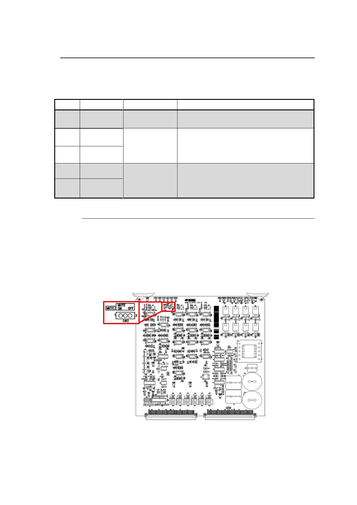
(1) Setting the ETR board
When a 38, 70, or 120 kHz ES is installed, set SW2 on the ETR-10
board inside the model SR-87 transducer to OFF. (See Fig. 4-15.)
The factory setting is OFF.
Fig. 4-15 ETR-10 board silk screen drawing and SW2
Note that in the case where an ES is installed, there are no changes
in the board settings.