4-4
DNW-A75/A75P
MAINTENANCE MODE
M0 : TAPE MAINTENANCE
M2 : ERROR LOGGER
M3 : OTHERS
M4 : SETUP MAINTENANCE
*
M0 -TAPE MAINTEN
4-1. Overview of Maintenance Mode
Activating the Maintenance Mode
1. Check that the video monitor is connected to the VIDEO OUTPUT COMPOSITE 3 (SUPER)
connector.
2. Press the 9 S1101 switch (on the SS-83 board).
3. The mode screen in the maintenance mode is superimposed on the video monitor.
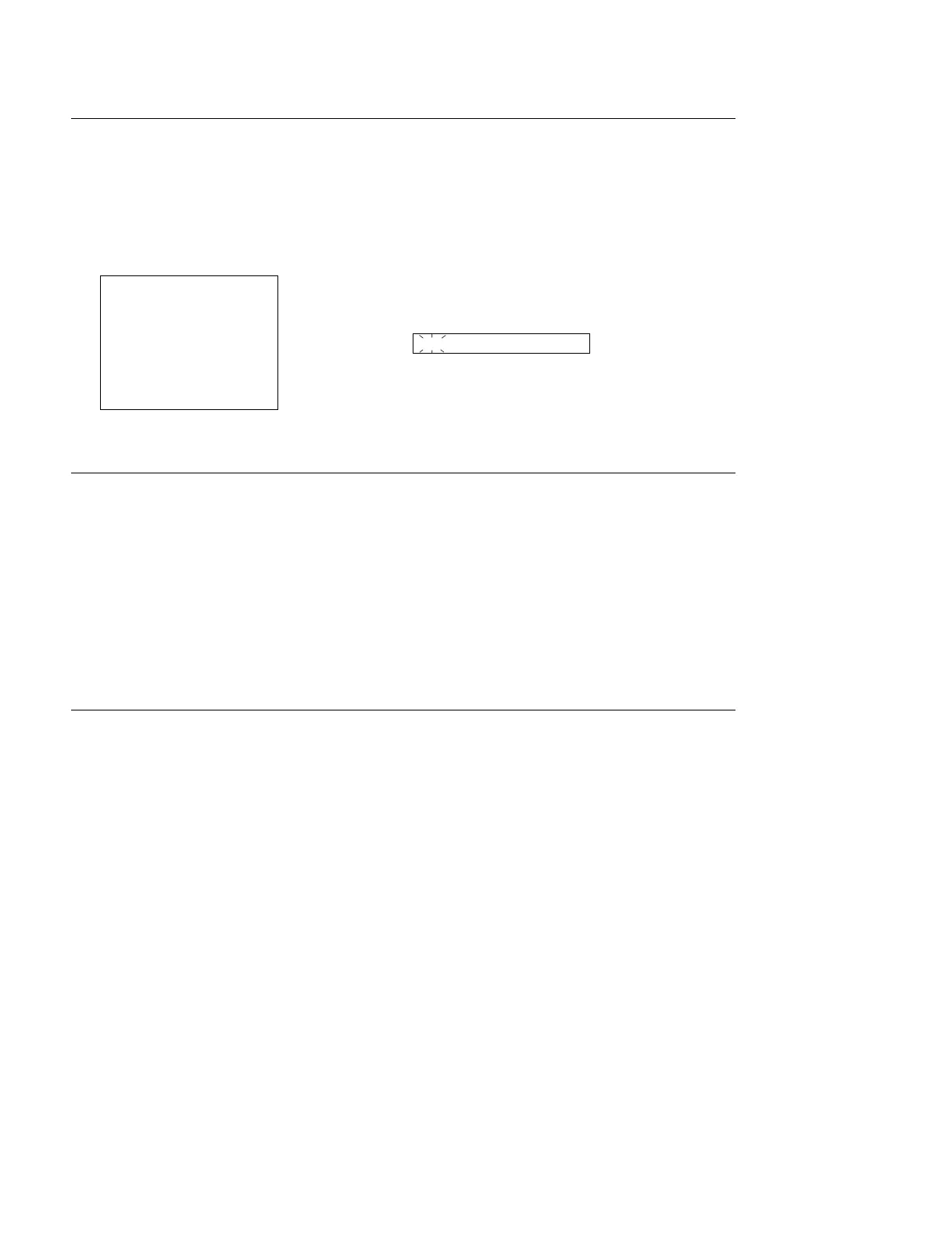
In a 1 time data display area, “M0-TAPE MAINTEN” is displayed and the M0 block blinks.
Video Monitor Time Data Display Area
Activating the Maintenance Mode from Control Panel
The maintenance mode can be activated by the operation below when the S1100-2 switch (on the SS-83
board) is set to ON (upper).
1. Press the 2 MENU button once.
(Execute the setup menu mode from the operation mode.)
2. Press the 3 SET button while pressing the 4 CTL/TC/UB button.
(Execute the maintenance mode from the setup menu mode.)
3. The mode screen in the maintenance mode is displayed on the video monitor.
Terminating the Maintenance Mode
1. Press the 2 MENU button several times to display the mode screen on the video monitor.
The selected mode No. and title are displayed in a time counter.
2. Press the 2 MENU button again to terminate the maintenance mode.