Debug support (DBG) RM0440
2100/2126 RM0440 Rev 4
47.16.2 Debug support for timers, RTC, watchdog and I
2
C
During a breakpoint, it is necessary to choose how the counter of timers,RTC and watchdog
should behave:
• They can continue to count inside a breakpoint. This is usually required when a PWM is
controlling a motor, for example.
• They can stop to count inside a breakpoint. This is required for watchdog purposes.
For the I
2
C, the user can choose to block the SMBUS timeout during a breakpoint.
The DBGMCU freeze registers can be written by the debugger under system reset. If the
debugger host does not support these features, it is still possible to write these registers by
software.
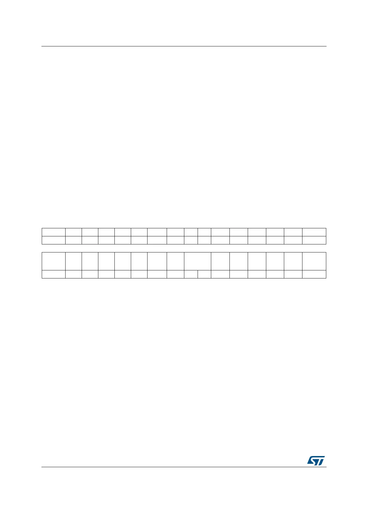
47.16.3 Debug MCU configuration register (DBGMCU_CR)
Address: 0xE004 2004
Power-on reset: 0x0000 0000
System reset: not affected
Access: Only 32-bit access supported
31 30 29 28 27 26 25 24 23 22 21 20 19 18 17 16
Res. Res. Res. Res. Res. Res. Res. Res. Res. Res. Res. Res. Res. Res. Res. Res.
15 14 13 12 11 10 9 8 7 6 5 4 3 2 1 0
Res. Res. Res. Res. Res. Res. Res. Res.
TRACE_
MODE
[1:0]
TRACE
_
IOEN
Res. Res.
DBG_
STAND
BY
DBG_
STOP
DBG_
SLEEP
rw rw rw rw rw rw
Bits 31:8 Reserved, must be kept at reset value.
Bits 7:5 TRACE_MODE[1:0] and TRACE_IOEN: Trace pin assignment control
– With TRACE_IOEN=0:
TRACE_MODE=xx: TRACE pins not assigned (default state)
– With TRACE_IOEN=1:
– TRACE_MODE=00: TRACE pin assignment for Asynchronous Mode
– TRACE_MODE=01: TRACE pin assignment for Synchronous Mode with a
TRACEDATA size of 1
– TRACE_MODE=10: TRACE pin assignment for Synchronous Mode with a
TRACEDATA size of 2
– TRACE_MODE=11: TRACE pin assignment for Synchronous Mode with a
TRACEDATA size of 4
Bits 4:3 Reserved, must be kept at reset value.
 Loading...


