Instruction Manual for AS380 Series Elevator Integrated Drive Controller
Chapter 6 Introduction to the supporting products
Table 6.7 instruction control board plug-in specification
Table 6.8 instruction control board port definition
the definition of 1#
instruction
controller pin
the definition of 2#
instruction controller
pin
the definition of 8#
instruction controller
pin
Connect 1
st
floor
instruction button
Connect 9th floor
instruction button
Connect 57th floor
instruction button
Connect 2nd floor
instruction button
Connect 10th floor
instruction button
Connect 58
th
floor
instruction button
Connect 3rd floor
instruction button
Connect 11th floor
instruction button
Connect 59
th
floor
instruction button
Connect 4th floor
instruction button
Connect 12th floor
instruction button
Connect 60th floor
instruction button
Connect 5th floor
instruction button
Connect 13th floor
instruction button
Connect 61st floor
instruction button
Connect 6th floor
instruction button
Connect 14th floor
instruction button
Connect 62nd floor
instruction button
Connect 7th floor
instruction button
Connect 15th floor
instruction button
Connect 63rd floor
instruction button
Connect 8th floor
instruction button
Connect 16th floor
instruction button
Connect 64th floor
instruction button
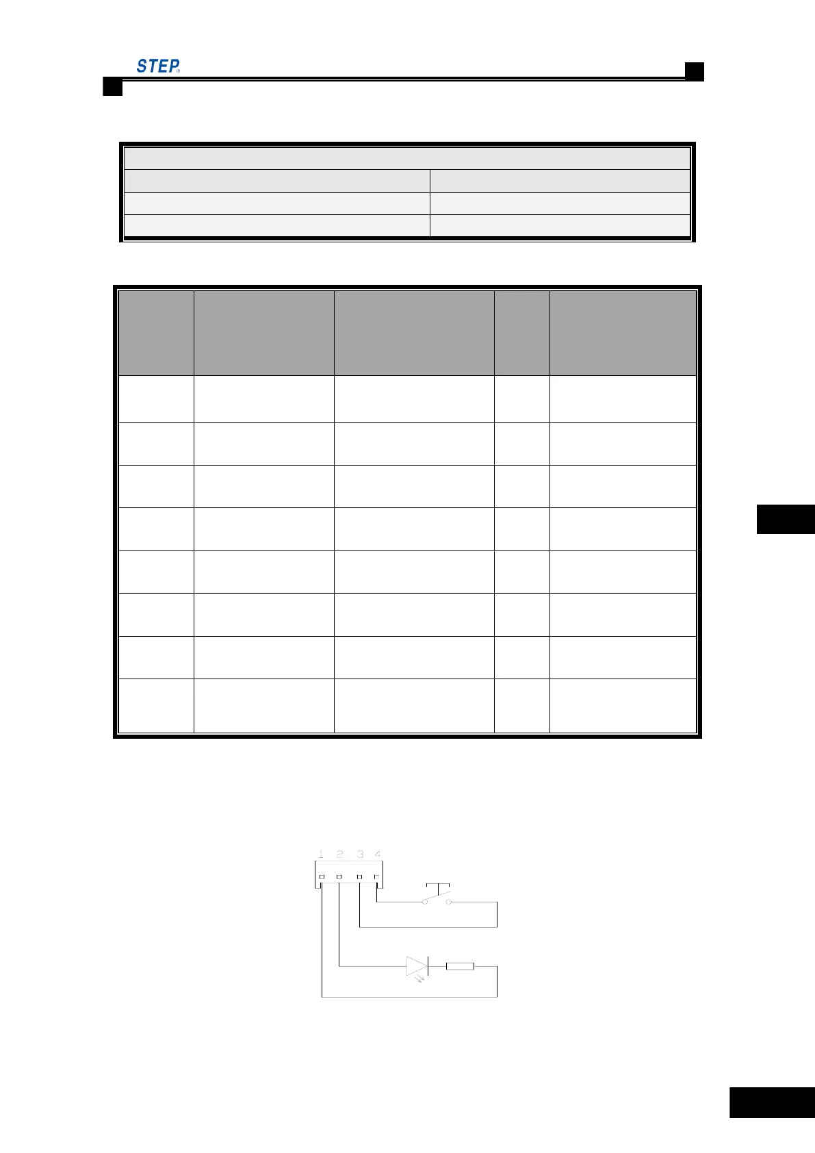
Note: instruction button and indicator lamp connection.
Pin 1 and 2 connect respectively to the ―-― and ―+‖terminal of power supply of indicator. And
pin 3 and 4 connect to the instruction button terminal.
Fig 6.10 instruction button and indicator lamp wiring diagram
Instruction controller board
JP1/JP2/JP3/JP4/JP5/JP6/JP7/JP8
14 pin parallel dot-matrix socket
 Loading...