Shanghai STEP Electric Corporation
Chapter 6 Introduction to the supporting products
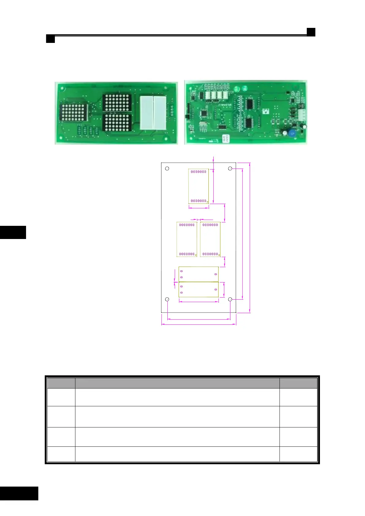
6.5.8 Call & LED display SM-04-VRJ
SM-04-VRJ outside view and installation dimension
Fig 6.29 SM-04-VRJ outside view
148.4
71.8
170
85
39.4
22.8
45
17
20.911.5
0.3
3.9
7
Fig 6.30 SM-04-VRJ installation dimension
◌SM-04-VRJ plug-in specification and port definition
Table 6.18 SM-04-VRJ plug-in specification and port definition
Serial port, of which Pin 1 for TXV+, Pin 2 for TXV-, Pin 3 for TXA+ and
Pin 4 for TXA- respectively.
Down-call terminals, of which Pin 1 -and Pin 2 + for button indicator, Pin 3
and Pin 4 for button input.
Up-call terminals, of which Pin 1- and Pin 2+ for button indicator, Pin 3 and
Pin 4 for button input.
Pin 3 and Pin 4 for the input of normal open contact of the lockout switch,
Pin 1 and Pin 2 for stand-by.
 Loading...