Instruction Manual for AS380 Series Elevator Integrated Drive Controller
Chapter 6 Introduction to the supporting products
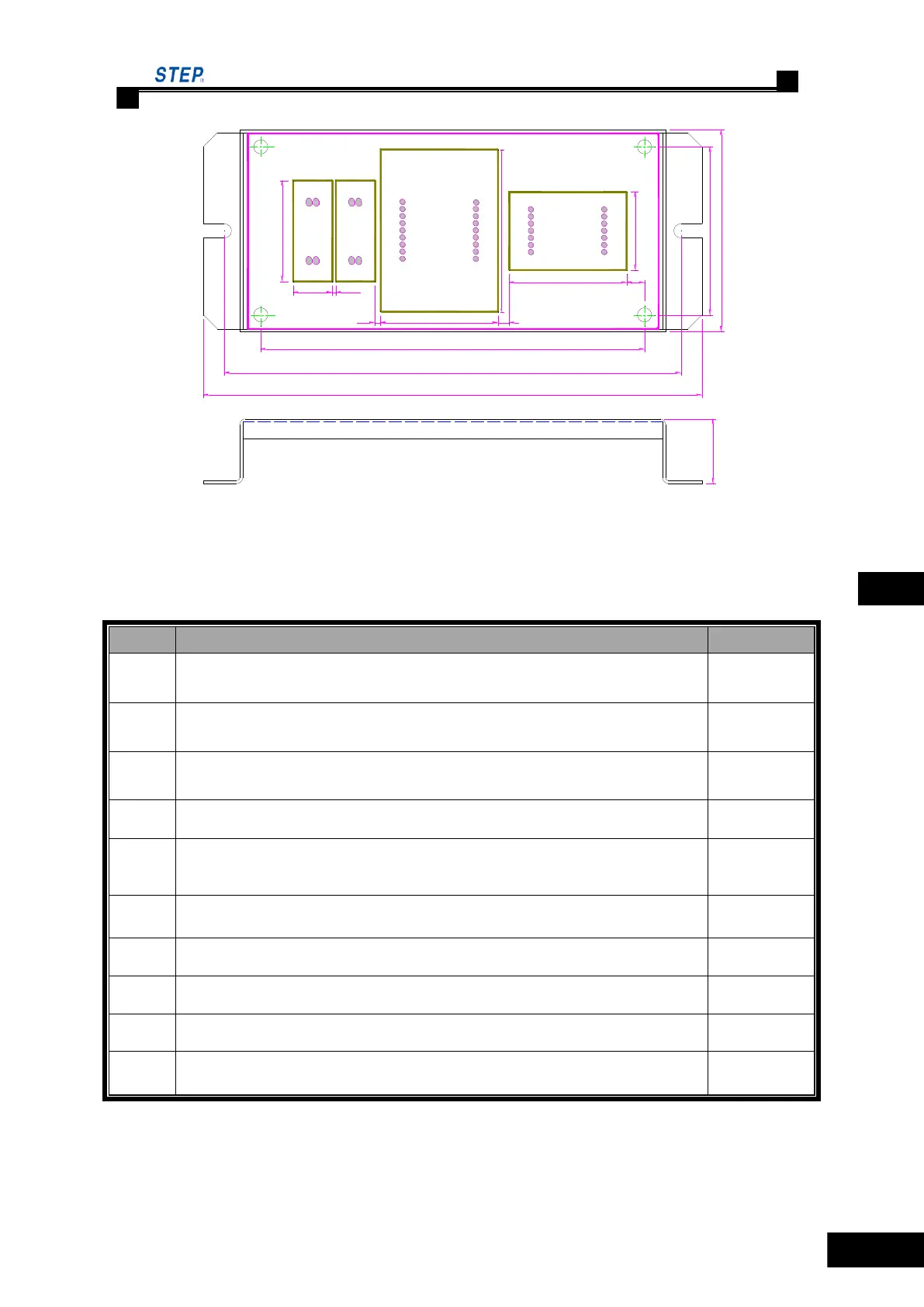
28
23
72
60
163
178
137
42
42
13.9
2 4
1.3
36
58
6.3
Fig 6.28 SM-04-VSD installation dimension
◌ SM-04-VSD plug-in specification and port definition
Table 6.17 SM-04-VSD plug-in specification and port definition
Program burning record slot/ RS232 communication port
Serial communication port, in which pin 1 is TXV+, pin 2 is TXV-, pin 3 is
TXA+, pin 4 is TXA-
Up-call terminals, of which Pin 1- and Pin 2+ for button indicator, Pin 3 and
Pin 4 for button input.
Down-call terminals, of which Pin 1- and Pin 2+ for button indicator, Pin 3
and Pin 4 for button input.
Pin 1 and Pin 2 is the elevator-lock indicator output, Pin 3 and 4 are Normal
open contact input of elevator-lock
Set the address codes of the display Board with the jumper on, after that the
jumper MUST BE REMOVED.
Bridge S2.1 and S2.2 to use JP2 as the button of three-wire system, otherwise ,
used as button for four wire system.
Bridge S3.1 and S3.2 to use JP3 as the button of three-wire system, otherwise,
used as button for four wire system
Resistor jumper of serial communication terminal, meanwhile shorting means
the connection of built-in 120Ω resistor.
 Loading...