Instruction Manual for AS380 Series Elevator Integrated Drive Controller
Appendix A EMC Installation Guide
thermorelay. Especially when small capacity elevator integrated drive controller under 7.5Kw is
used, and at the same time, long wiring (more than 50m) is provided, the increased leakage current
is liable to make malfunction of external thermorelay.
Suppression Measures: reduce carrier frequency; install AC output reactor at the output side;
monitor the motor temperature directly with the temperature sensor; or use electronic thermorelay,
the motor overload protection integrated to elevator integrated drive controller instead of external
thermorelay,
A6 Suppression of Radiated Emission
Elevator integrated drive controller is usually installed in metal control cabinet, the external
instruments and equipments are lightly affected by radiated emission of elevator integrated drive
controller. Therefore, the external connecting cables are deemed as the main source of radiated
emission. Due to the supply cable, motor cable as well as the control cable and keyboard cable are
all necessary to be led outside of the shielding cabinet; the cable outlet must be so treated specially
to avoid impairing the shielding effects.
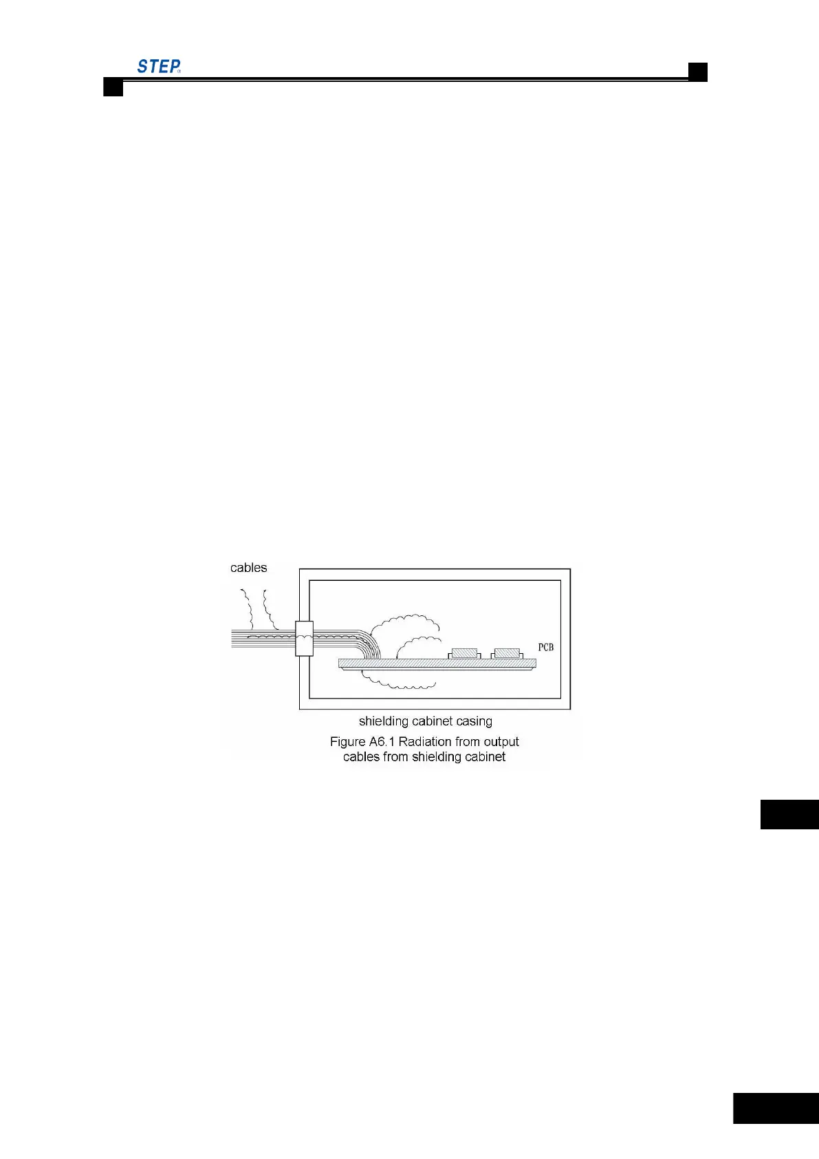
In Figure A6.1: the cables in the shielded cabinet acts as an antenna, which absorbs the radiated
noises in cabinet, transmits outside via cables and emits them to the space; in Figure A6.2: ground
the cable‘s shielding layer at the outlet of the shielded cabinet, thus the noise radiation absorbed
by the cable will flow to earth directly via the shielding cabinet so as to eliminate its effect on
external environment.
When using the shielding layer grounding method as shown in figure A6.2, the shielding layer
must be grounded as close to the cabinet as possible, otherwise the sectional cable from grounding
point to the outlet of cabinet will still act as an antenna coupling. The noise grounding point shall
not be more than 15cm from cable outlet of cabinet, and smaller clearance will always be more
preferable.
 Loading...