Instruction Manual for AS380 Series Elevator Integrated Drive Controller
Chapter 4 The Wiring Of Elevator integrated Drive Controller
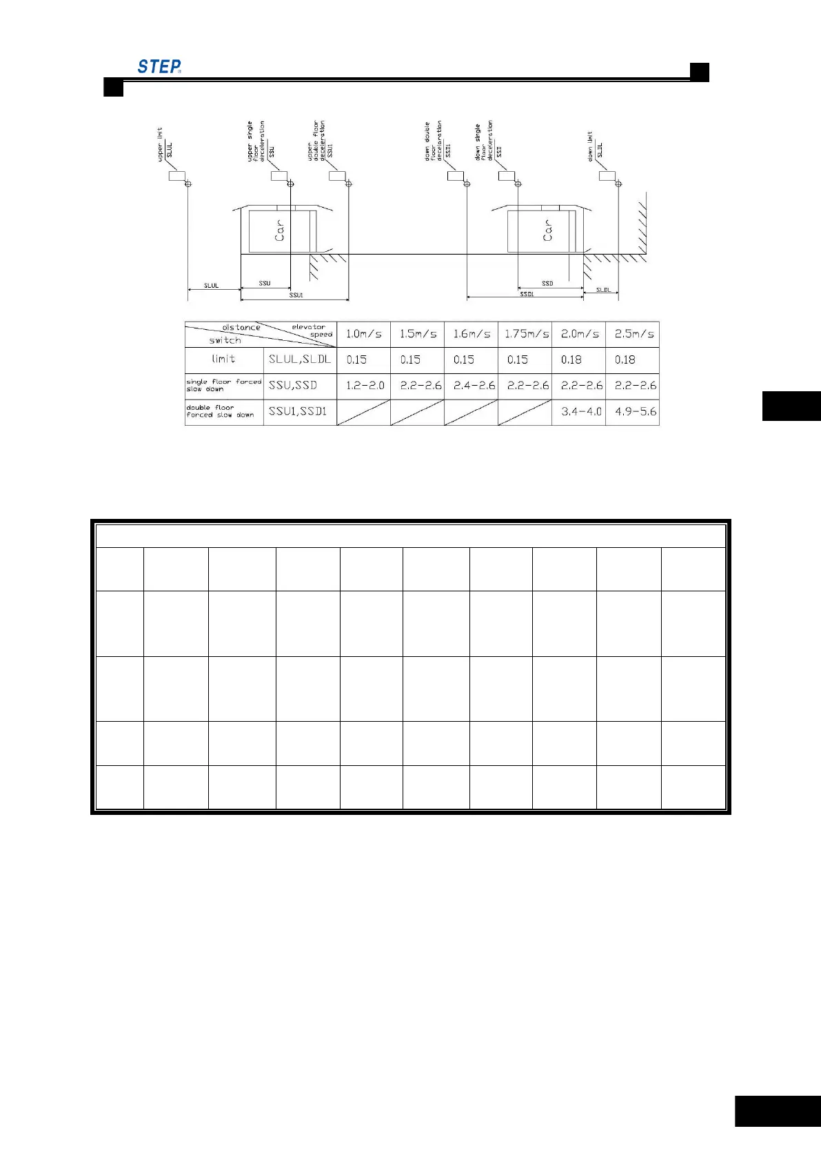
Figure 4.4 Detailed Locations of Shaft Switches
Table 4.1 installation clearance of deceleration switch in hoist way
Installation clearance of deceleration switch in hoist way
4.3.4 Upper and Lower Leveling Inductor
In elevator integrated drive control system, two pairs of up and down leveling inductor and several
magnet vanes are required by the elevator leveling control to install on site. Furthermore, where
PRE-OPENING or PRE-OPENING AND RE-LEVELING function is set, additional two door
range inductors must be installed. See Table 4.1 for detailed requirements of inductor and
magnetic vane.
 Loading...