Instruction Manual for AS380 Series Elevator Integrated Drive Controller
Chapter 4 The Wiring Of Elevator integrated Drive Controller
4.4 main circuit terminal wiring
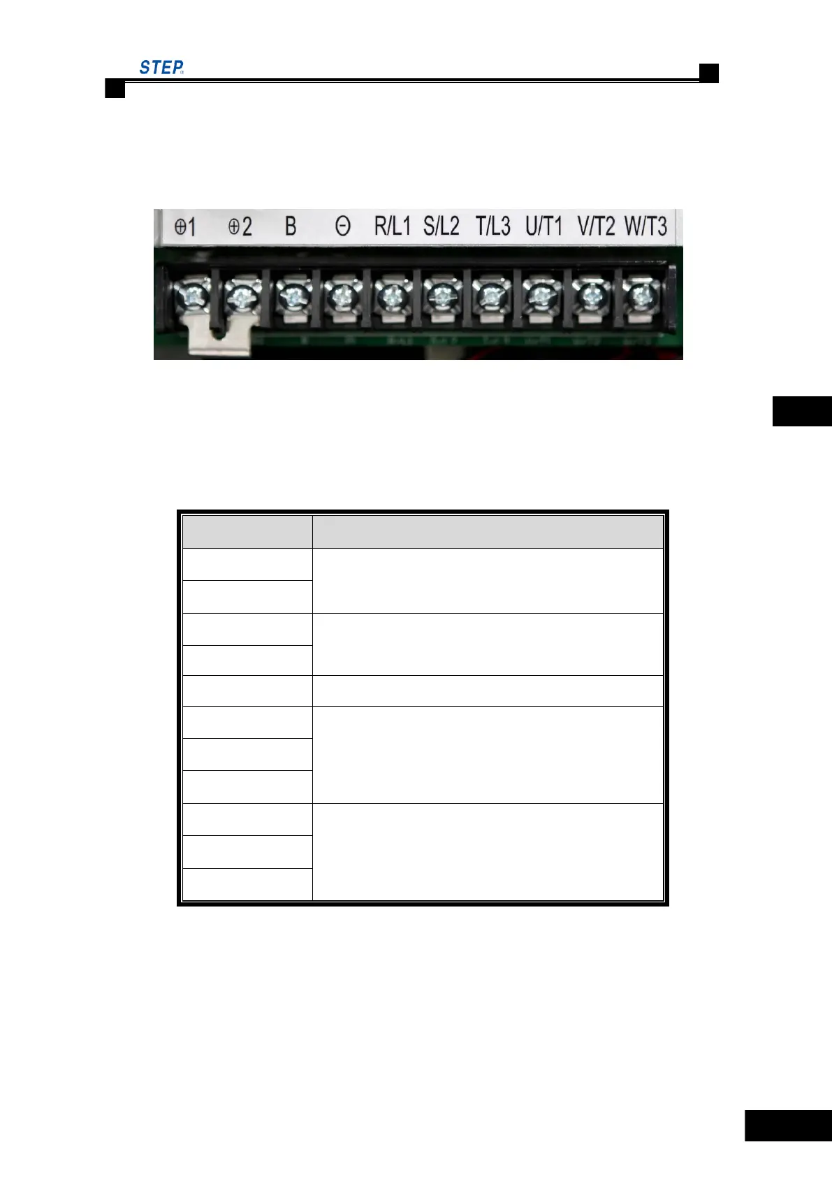
4.4.1 The arrangement of main circuit terminal
4.4.2 The main circuit terminal labeling and function description
Please take reference to table 4.1 for main circuit terminal function description
Table 4.1 main circuit terminal function description
Terminal function description
DC reactor can be connected. Shorting before delivery
external brake resistor connected
DC bus negative output terminal
Main circuit AC power input, three-phase input power
supply connected.
Integrated drive controller output, three phase
synchronous/asynchronous motor connected.
4.4.3 Main circuit wire specification
The conductor is 600V copper-core plastic insulation conductor for power supply. See Table 4.2
for conductor specification and fastening torque.
 Loading...