EasyManuals Logo

STEP AS380 Series User Manual

Default Icon
300 pages
To Next Page IconTo Next Page
To Previous Page IconTo Previous Page
Page #52 background imageLoading...
Page #52 background image
Shanghai STEP Electric Corporation
42
Chapter 4 The Wiring Of Elevator integrated Drive Controller
4.6 Wiring of Control Circuit Terminals
4.6.1 Layout of Control Circuit Terminals
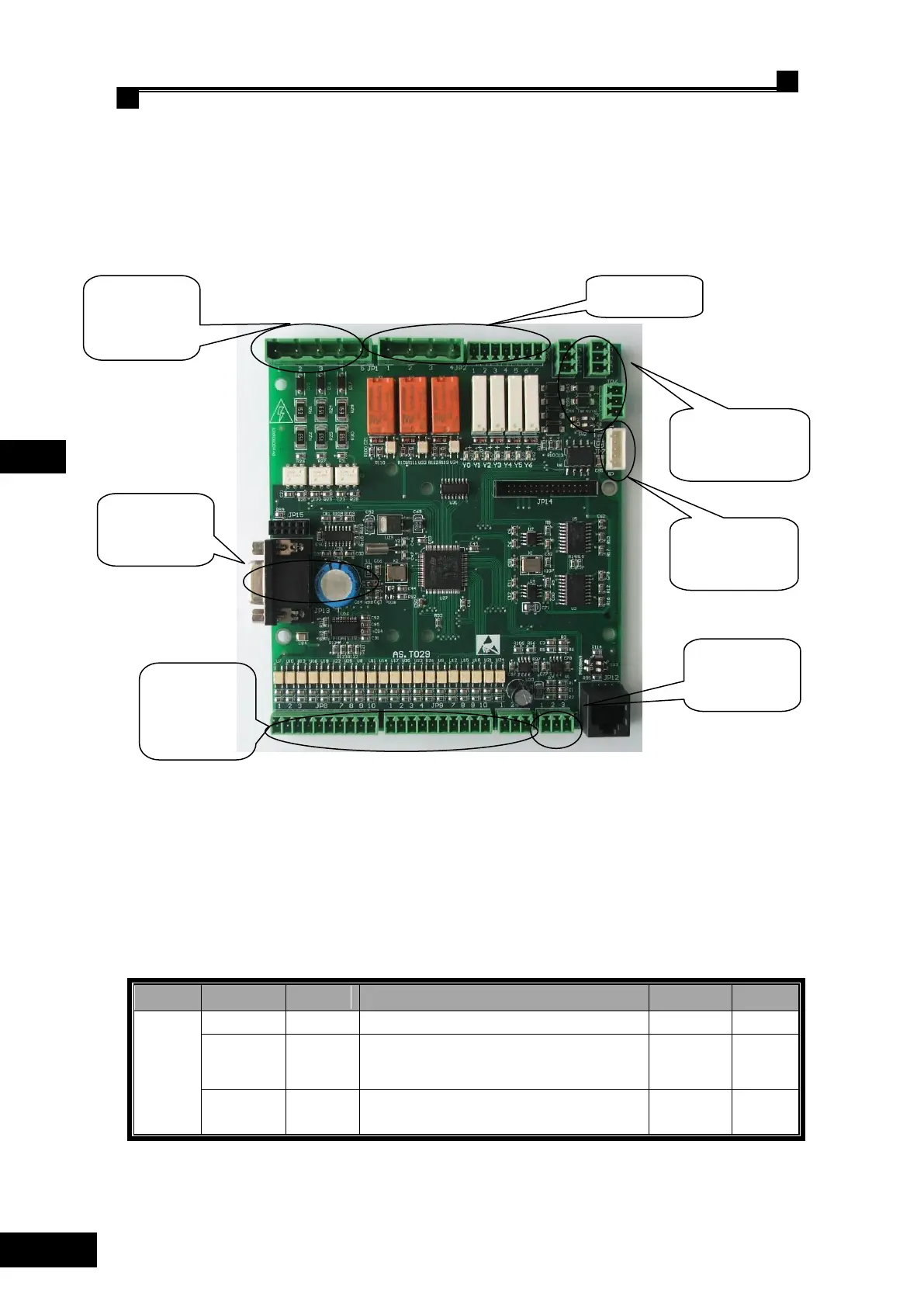
Layout of control circuit terminals is as shown in Fig.4.17.
Fig .4.17 Control Circuit Terminals
4.6.2 Functional Description of Control Circuit Terminals
See Table 4.4 for functional description of control circuit terminals.
Table 4.4 Functional Description of Control Circuit Terminals
No
location
name
Definition
type
remark
JP1
JP1.1
XCOM
X20-X22 input signal common port 0V
JP1.2
X20
safety circuit inspection positive voltage port
110V/220V input
Input
JP1.3
X21
door lock circuit inspection positive voltage
port110V/220V input
Input
CAN
communication
Isolating power
input
Analog
amount input
low-voltage
opto-coupler
input
Extensive
board port
Relay output
High-voltage
opto-coupler
input

Table of Contents

Questions and Answers:

Question and Answer IconNeed help?

Do you have a question about the STEP AS380 Series and is the answer not in the manual?

STEP AS380 Series Specifications

General IconGeneral
BrandSTEP
ModelAS380 Series
CategoryController
LanguageEnglish

Related product manuals