Instruction Manual for AS380 Series Elevator Integrated Drive Controller
Chapter 4 The Wiring Of Elevator integrated Drive Controller
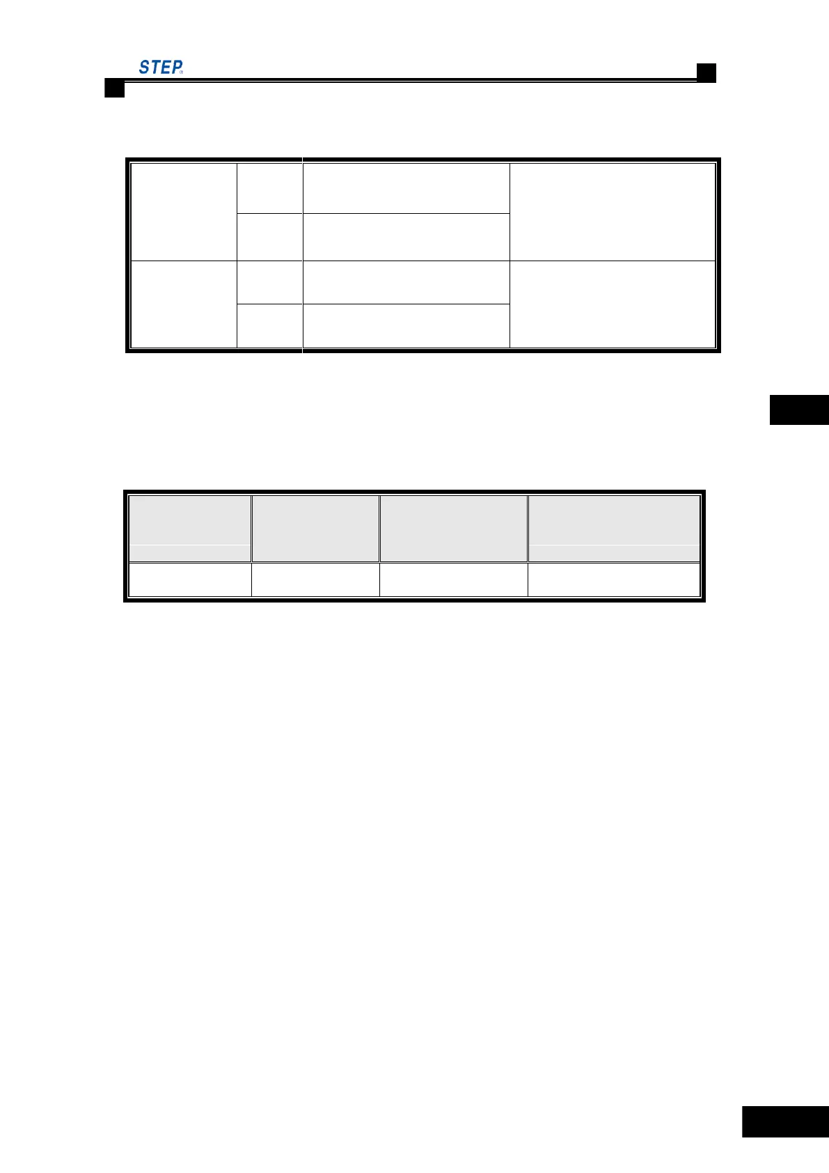
4.6.3 Dip switch setting method
Monitoring CAN terminal
resistor effective condition
SW2 default setting is OFF;
Monitoring CAN terminal
resistor invalid condition
program recording condition
Default setting is OFF
(keep OFF condition when in
use)
4.6.4 Wire specification of control circuit
The control circuit should adopt the 600V pressure-proof plastic insulated copper core wire. The
wire specification and fastening torque see table 4.5
Table 4.5 wire specification and fastening torque
Spec of connectible
wire mm
2
Spec of recommended
wire mm
2
The wire specification is subject to the surrounding temperature 50℃ and allowable wire
temperature 75℃.
 Loading...