Instruction Manual for AS380 Series Elevator Integrated Drive Controller
Chapter 6 Introduction to the supporting products
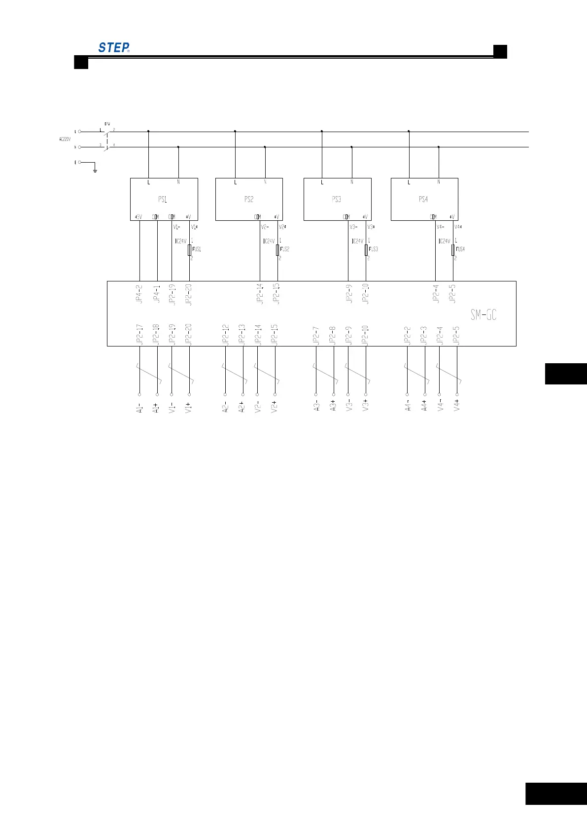
6.6.8 Connection Method of Group Control System
Fig. 6.38 Connection sketch diagram of group control cabinet
PS1, PS2, PS3, and PS4 are switch power supply, PS1 has +5V (3A) and +24V (1.8A)
output,PS2, PS3 and PS4 have only +24V(1.8A) output. FU1, FU2, FU3 and FU4 are
over-current protection devices. SM.GC/C is group control board.
This figure shows the schematic for group control of four elevators.
6.6.9 Setting of Group Control Operation
This chapter mainly introduces the setting of group control operation.
1) Wiring Connection
After the single elevator‘s operation, do the group control system‘s commissioning.
Connecting the group control cabinet, and according the appointed agreement of the contract,
connect No. 1 elevator which has been appointed in the contract to the output port of
JP2.17~JP2.20 of group controller, connect No. 2 elevator to the output port of JP2.13~JP2.16 and
etc. If the total floors, stop floors or serial number of elevators in the group control system are
changed which are discordant with the agreement of the contract in the site, please inform
Shanghai STEP Electric Co., Ltd. Oherwish, unpredictable problem would happen, and the group
control would fail.
 Loading...