Instruction Manual for AS380 Series Elevator Integrated Drive Controller
Chapter 6 Introduction to the supporting products
downward call button port (pin 1,2 as button lamp indicator, 1 as ―-―, 2 as ―+‖, pin 3
and 4 as button input
stop indicator( hall)/overload output (car) and elevator lock input port (pin 1,2 as
button lamp indicator, 1 as ―-―, 2 as ―+‖, pin 3 and 4 as normal open contact input of
elevator lock switch)
Full-load indicator( hall)/firefighting output (car) (pin 1,2 as button lamp indicator, 1
as ―-―, 2 as ―+‖, pin 3 and 4 as standby input)
program burning slot/RS232 communication port
Plug in jumper to set the address code of the display board and remove the jumper
after the setting complete
Bridge S2.1 and S2.2 and use JP2 as the button of three wire system, bridge S2.2 and
S2.3 ( or do not bridge) as the button of four wire system
Bridge S3.1 and S3.2 and use JP3 as button of three-wire system, bridge S3.2 AND
s3.3 ( or do not bridge) as button of four wire system
Resistor jumper of serial communication terminal and shortening mean the connection
to the built-in 120 ohm resistor
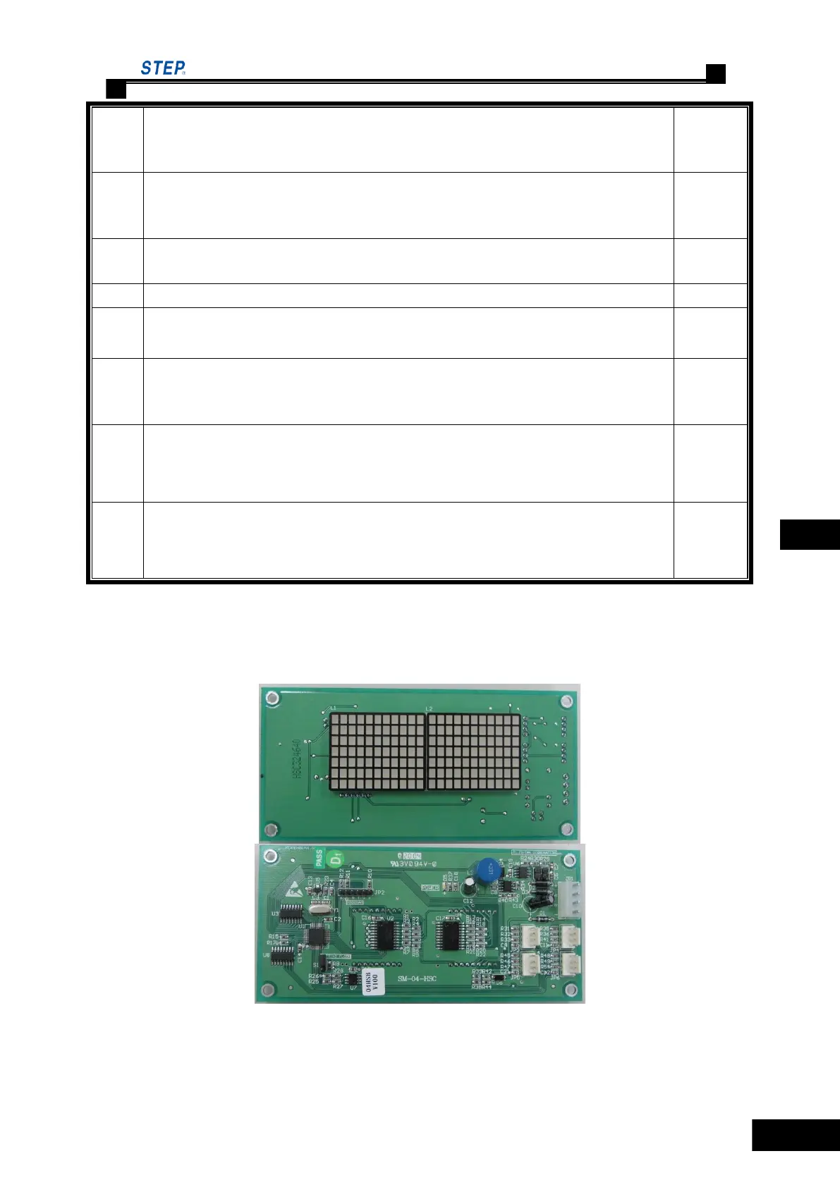
6.5.2 Call& display control board SM-04-HSC
Outside View & Mounting Dimensions of SM-04-HSC
Fig. 6.17 Outside View of SM-04-HSC
 Loading...