Shanghai STEP Electric Corporation
Chapter 6 Introduction to the supporting products
7
23
1
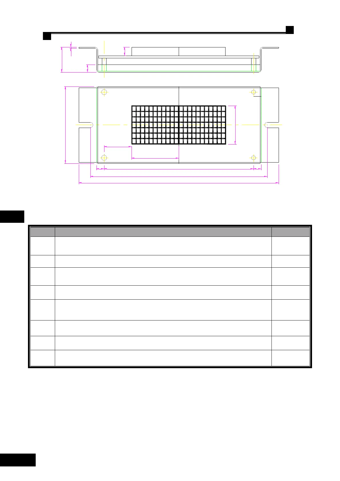
182.5
161.5
70
7 7136.5
43
35
25.25
8
Fig. 6.18 Mounting Dimensions of SM-04-HSC
◌ Terminal Definition and Plug-in Specification on SM-04-HSC
Serial port, of which Pin 1 for TXV+, Pin 2 for TXV-, Pin 3 for TXA+ and Pin 4 for
TXA- respectively.
RS232 port / program burn recording slot.
Up-call terminals, of which Pin 1- and Pin 2+ for button indicator, Pin 3 and Pin 4 for
button input.
Down-call terminals, of which Pin 1- and Pin 2+ for button indicator, Pin 3 and Pin 4
for button input.
Stop indicator (Landing)/Over load output(In-Car) and lockout input terminals, of
which Pin 1- and Pin 2+; Pin 3 and Pin 4 for the normal open contact input of the
lockout switch.
full-load indicator (Landing)/fire indicator (In-Car), of which Pin 1- and Pin 2+ for
light indicator; Pin 3 and Pin 4 for stand-by.
Set the address codes of the display Board with the jumper on, after that the jumper
MUST BE REMOVED.
Resistor jumper for serial communication terminals for connecting the 120Ω built-in
resistor when jumpers are put on together.
List 6.12 Terminal Definitions and Specification of SM-04-HSC
6.5.3 Call & Display Control Board SM-04-VHL
◌ Outside View & Mounting Dimensions of SM-04-VHL
 Loading...