Shanghai STEP Electric Corporation
Chapter 4 The Wiring Of Elevator integrated Drive Controller
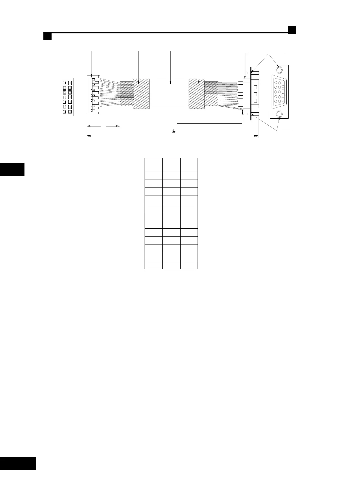
Weld The shielded layer on metal part of DB plug
310
C1
Plastic
shell2*7
C2
DB15
female
PIN3
PIN4
PIN5
PIN6
PIN7
PIN8
PIN9
PIN 10
PIN 11
PIN 12 PIN 11
PIN 10
PIN 12
PIN 13
PIN 5
PIN 6
PIN 8
PIN 1
PIN 3
PIN 4
Maching
cloor
Red
Red/white
Orange
Orange/
black
Green
Note: DB15 female plug is fixed by its outside plastic casing shell,
and is fasten locked by the M3 nuts at the both ens of the plasitic
casing shell.
1 44
PIN 13
PIN 14 PIN 9
PIN 7 Black
Yellow
Blue
25
10
C1
C2
1
2
13
14
3
1
5
11
15
6
10
M3 nut
M3 nut
Yellow/
black
Green/
black
Blue/
black
Black/
white
2
Fig. 4.29 Specification for SIN/COS PG card encoder signal transformation cable
4.7.3 PG card – Incremental ABZ 5V
Incremental ABZ 5V PG card (AS.T041) can receive three kinds encoder signals. It can talk
to the encoder with open collector signal, push-pull signal and differential signal.
4.7.3.1 Line-up terminal for incremental ABZ 5V PG card
Terminal line up for incremental ABZ 5V PG card (AT.T041), see Fig. 4.30.
 Loading...