EasyManuals Logo

STEP AS380 Series User Manual

Default Icon
300 pages
To Next Page IconTo Next Page
To Previous Page IconTo Previous Page
Page #117 background imageLoading...
Page #117 background image
Instruction Manual for AS380 Series Elevator Integrated Drive Controller
Chapter 6 Introduction to the supporting products
107
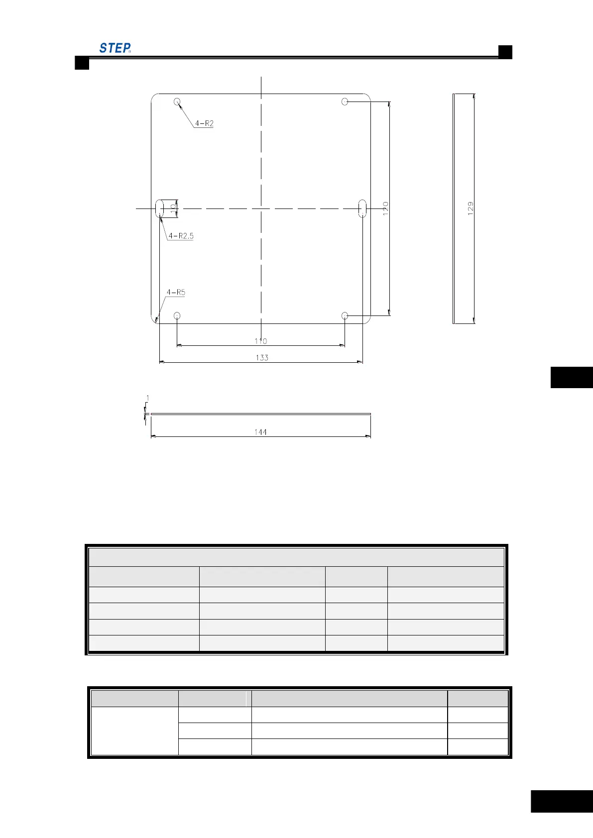
Fig 6.2 car top control baseboard installation dimension
6.1.2 Car top control panel SM 02/H
Table 6.1 car top control panel SM.02/H plug-in specification
Table 6.2 Car top control panel SM.02/H input and output port definition
Socket No
Port No
Definition
Remark
JP1
1
24V red
2
GND yellow
3
CANH green
Car top control panel SM-2/H plug-in specification
Pin No.
Type
Pin No.
Type
JP1
CH3.96-4A
JP5
5.08-3P-V-green
JP2
IDC-14P
JP6
5.08-4P-V-green
JP3
5.08-5P-V-green
JP7
CH2510-10A
JP4
5.08-7P-V- green
JP8
5.08-2P-V-green

Table of Contents

Questions and Answers:

Question and Answer IconNeed help?

Do you have a question about the STEP AS380 Series and is the answer not in the manual?

STEP AS380 Series Specifications

General IconGeneral
BrandSTEP
ModelAS380 Series
CategoryController
LanguageEnglish

Related product manuals