Instruction Manual for AS380 Series Elevator Integrated Drive Controller
Chapter 4 The Wiring Of Elevator integrated Drive Controller
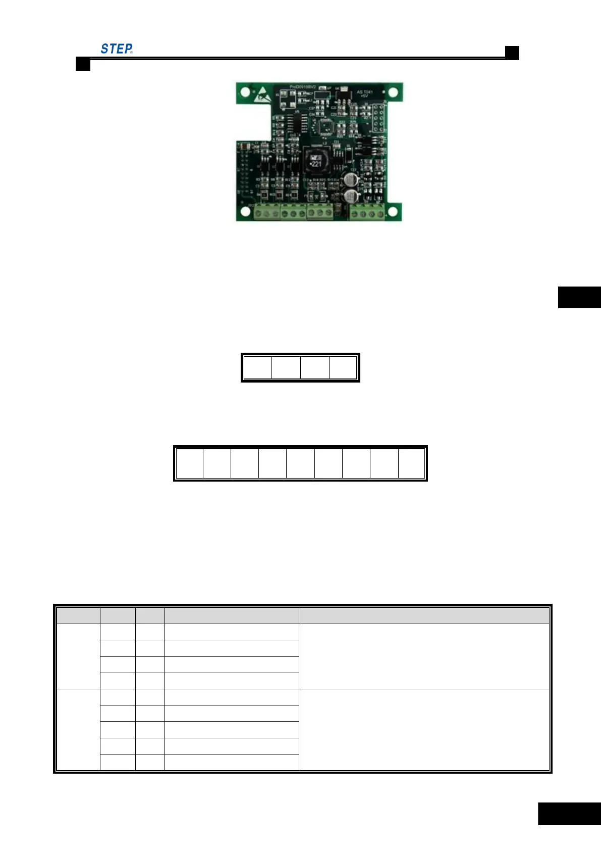
Fig. 4.30 Terminal line up for incremental ABZ 5V PG card
4.7.3.2 Incremental ABZ 5V PG card terminal label
Terminal label for incremental ABZ 5V PG card is as follows:
JP3 divided frequency output terminal:
Fig. 4.31 The connection terminal JP3 lables of the Incremental ABZ 5V PG card
JP2 input terminal:
Fig. 4.32 The connection terminal JP2 lables of the Incremental ABZ 5V PG card
4.7.3.3 Incremental ABZ 5V PG card terminal function specification
Incremental ABZ 5V PG card terminal function specification, see table 4.10.
Table 4.10 Incremental ABZ 5V PG card terminal function specification
Divided frequency output, phase A
Triode open collector (max. output frequency 100kHz)
Divided frequency output, phase B
Phase A signal + of encoder power
Open collector/push-puff/differential, max input frequency 100kHz
Phase A signal - of encoder power
Phase B signal + of encoder power
Phase B signal - of encoder power
Phase Z signal + of encoder power
 Loading...