Instruction Manual for AS380 Series Elevator Integrated Drive Controller
Chapter 6 Introduction to the supporting products
Dimension specification:Outside Dimension: 160 x 109 cm,
LCD display dimension: 110 x 86 cm
Working temperature:-10 degree---60 degree
Working humidity:<95%
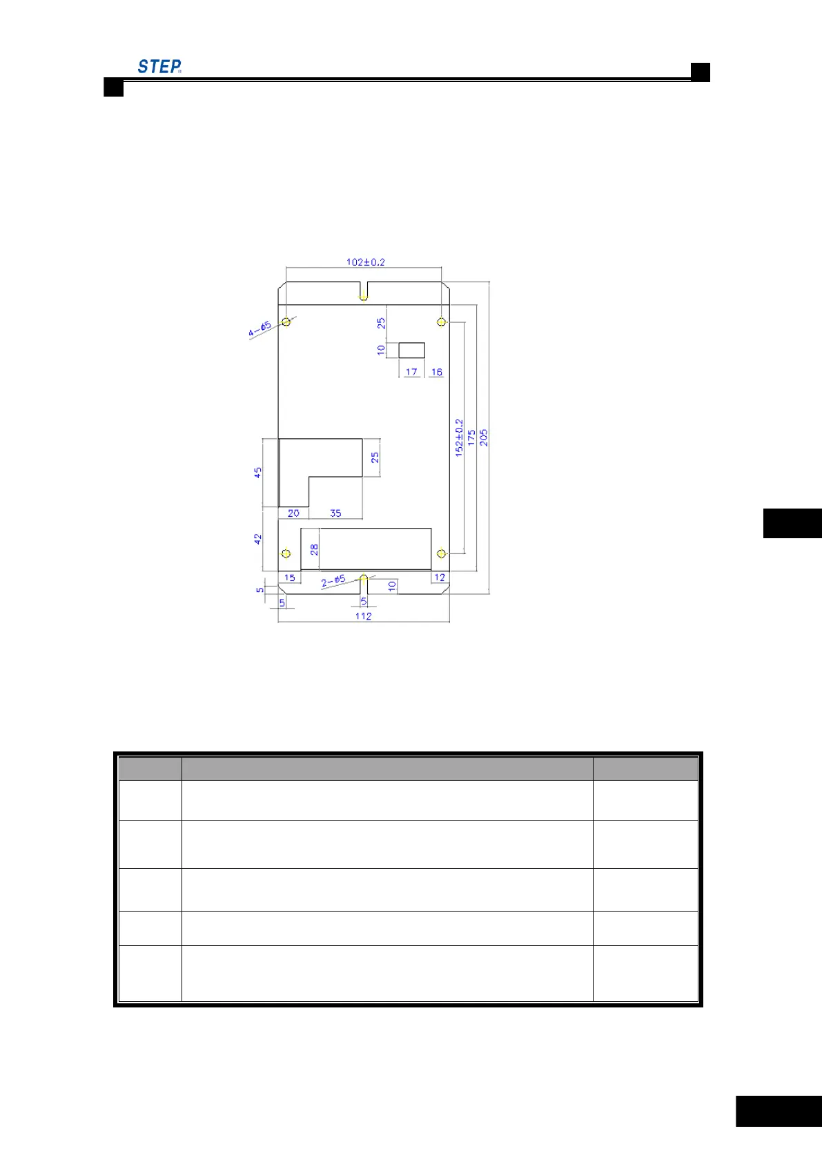
55 outside view and installation size
Fig. 6.22 outside View of SM-04-UL
◌ Terminal Definition and Plug-in Specification on SM-04-UL
Table 6.14 Terminal Definitions and Specification of SM-04-UL
Serial port, of which Pin 1 for TXV+, Pin 2 for TXV-, Pin 3 for
TXA+ and Pin 4 for TXA- respectively.
Down-call terminals, of which Pin 1 -and Pin 2 + for button
indicator, Pin 3 and Pin 4 for button input.
Up-call terminals, of which Pin 1- and Pin 2+ for button indicator,
Pin 3 and Pin 4 for button input.
Pin 3 and Pin 4 for the input of normal open contact of the lockout
switch, Pin 1 and Pin 2 for stand-by.
Resistor jumper for serial communication terminals for connecting
the 120Ω built-in resistor when jumpers are put on together. Both
ON for connection of CAN terminal resistor, both OFF for
disconnection of it.
 Loading...