Instruction Manual for AS380 Series Elevator Integrated Drive Controller
Chapter 4 The Wiring Of Elevator integrated Drive Controller
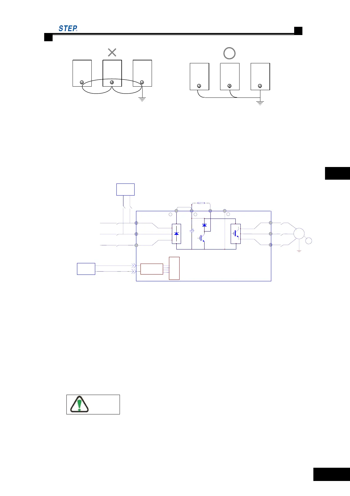
Fig 4.5 multi-elevator integrated drive controllers wiring
4.4.5.2 +48V DC connecting terminal
a) When encountering the blackout, battery will be activated to supply +48V DC low voltage
Power through R.S terminal to elevator integrated drive controller , and elevator will run
at low speed to get leveling at nearest floor.
b) UPS and battery wiring diagram 4.6
Fig 4.6 schematic diagram of emergency power supply and battery wiring
4.4.5.3 main circuit power input terminal (R/L1,S/L2,T/L3)
a) three-phase AC power supply is connected to the main circuit terminal R/L1,S/L2,T/L3
through breaker. The phase sequence of input power supply has nothing to do with the
sequence of R/L1,S/L2,T/L3 terminal, any of which is available for connection.
b) In order to reduce the possible conduction and radiation interference caused by elevator
integrated drive controller upon input power supply, noise filters should be installed on
the side of power supply. the noise filter can lower the magnetic noise penetration from
power line into the elevator integrated drive controller as well as vice verse.
Special note: please use the specialized noise filter of elevator integrated drive controller.
The right setting of noise filter at the side of power supply is as fig 4.7
 Loading...