Instruction Manual for AS380 Series Elevator Integrated Drive Controller
Chapter 4 The Wiring Of Elevator integrated Drive Controller
Fig 4.10 external connected shorting block wiring
Fig 4.11 external connected DC reactor wiring
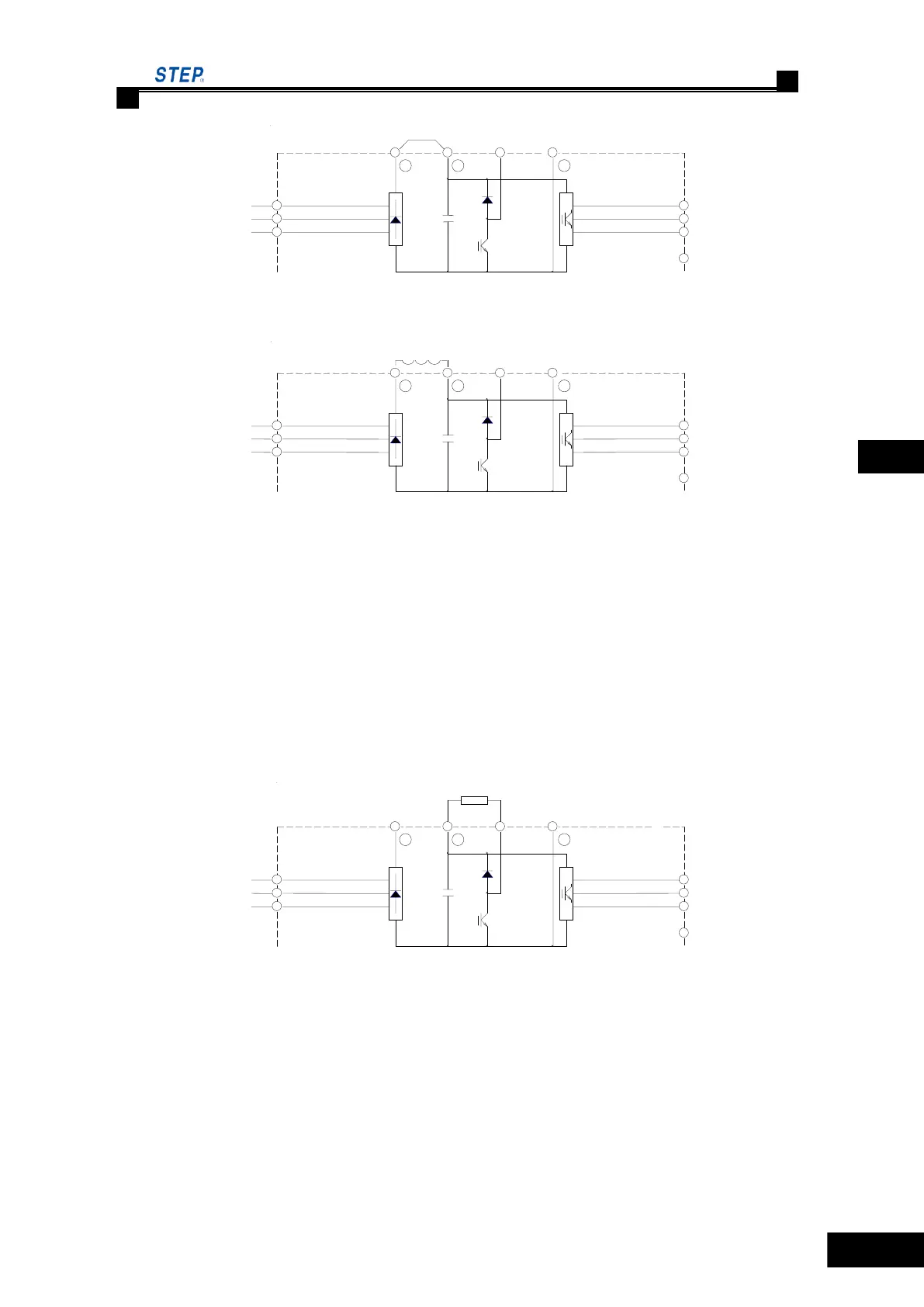
4.4.5.5 external-connected braking resistor terminal ( ○+2,B)
a) There are braking unit in all type of AS380 elevator integrated drive controller. in order to
release the feedback energy of braking motor, braking resistor must be connected externally, the
specification of braking resistor see the table 1.6.1 braking resistor configuration of chapter 1.
b) the braking resistor must be installed between ( ○+2,B) terminal.
c) in order to make the braking resistor work well, the heat dissipation of brake resistor must
be taken full consideration. Good ventilation is must.
d) The wire length of braking resistor should not be more than 5 meter.
The wiring of external connected braking resistor is as fig 4.12
Fig 4.12 external connected braking resistor wiring
4.4.5.6 elevator integrated drive controller output terminal (U/T1,V/T2,W/T3)
a) the output terminal of elevator integrated drive controller U/T1、V/T2、W/T3 and motor
terminal U、V、W are connected. If the rotating direction of motor is not right, please exchange the
wires of any two phase of the elevator integrated drive controller output terminal or motor
terminal.
b) connection between power supply output and elevator integrated drive controller output
terminal U/T1、V/T2、W/T3 is prohibited.
 Loading...