6-32 FI SYSTEM/ CVT SYSTEM
n
hi
V
3
3
Ye s
No
Red, P/B or B/Br wire open or shorted to ground, or poor
h
,
i
or
n
connection.
If wire and connection are OK, intermittent trouble or faulty
ECM.
Recheck each terminal and wire harness for open circuit
and poor connection.
Replace the ECM with a new one,
and inspect it again.
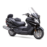
Connect the TP sensor coupler.
Insert the copper wires to the lead wire coupler.
Turn the ignition switch ON.
Measure the TP sensor output voltage at the coupler (be-
tween Yellow and Gr or R wires) by turning the throttle grip.
;
TP sensor output voltage
Throttle valve is closed : Approx. 1.1 V
Throttle valve is opened : Approx. 4.3 V
z
09900-25008: Multi circuit tester
u
Tester knob indication: Voltage (
-
)
If check result is not satisfactory,
replace TP sensor with a new one.
Yellow
Gr or R
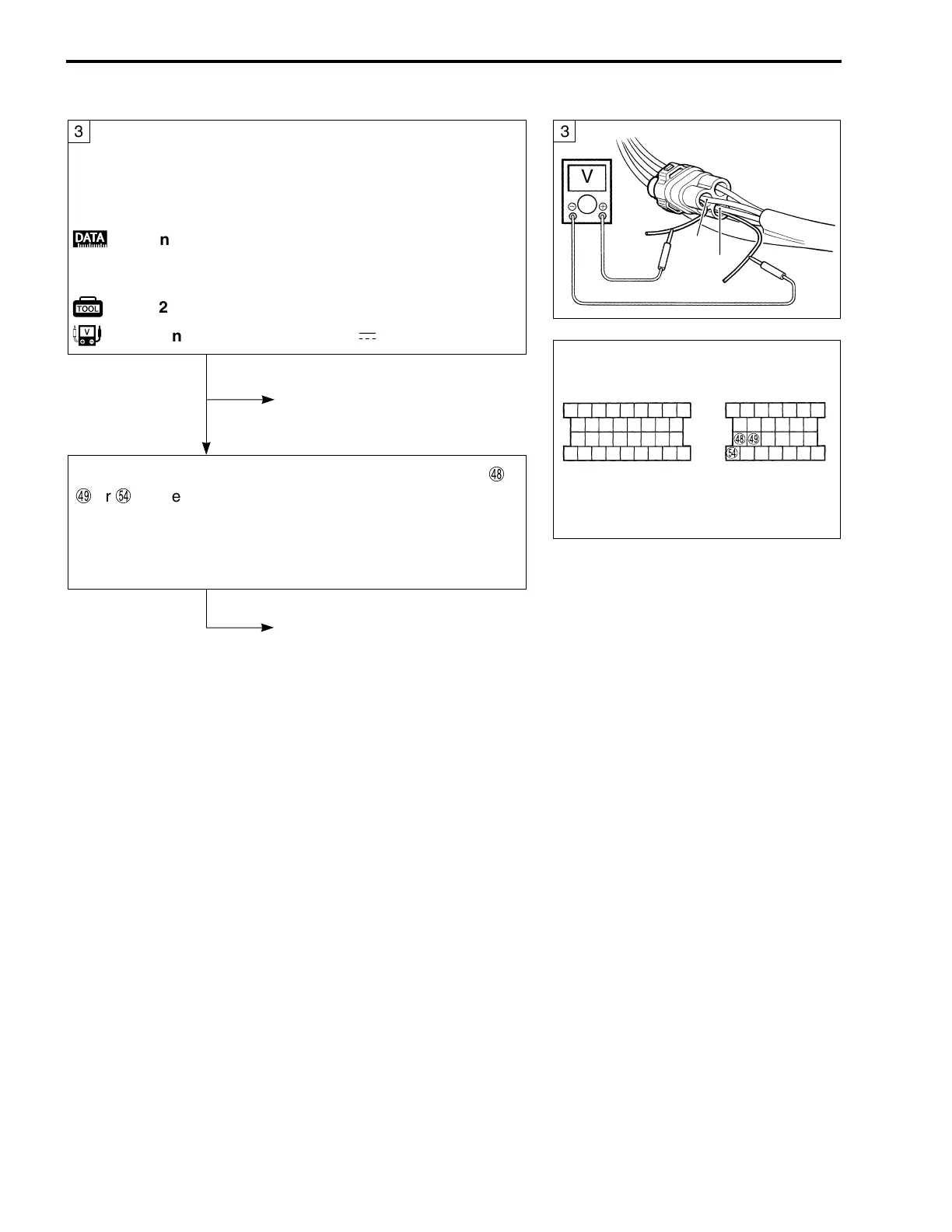
ECM couplers

 Loading...