EasyManua.ls Logo

Sysmac CQM1 User Manual

Default Icon
159 pages
To Next Page IconTo Next Page
To Previous Page IconTo Previous Page
Page #105 background imageLoading...
Page #105 background image
3-6SectionProgramming Console Operations
93
2. Input the address where the NO condition will be deleted and press the
Down Arrow Key. It is not necessary to input leading zeroes.
C
2
A
0
F
5
00205READ
AND 00103
3. Press the DEL Key.
DEL
00205DELETE?
AND 00103
4. Press the Up Arrow Key to delete the specified instruction.
If the instruction has more operands, the operands will be deleted automati-
cally with the instruction.
00205DELETE END
AND 00105
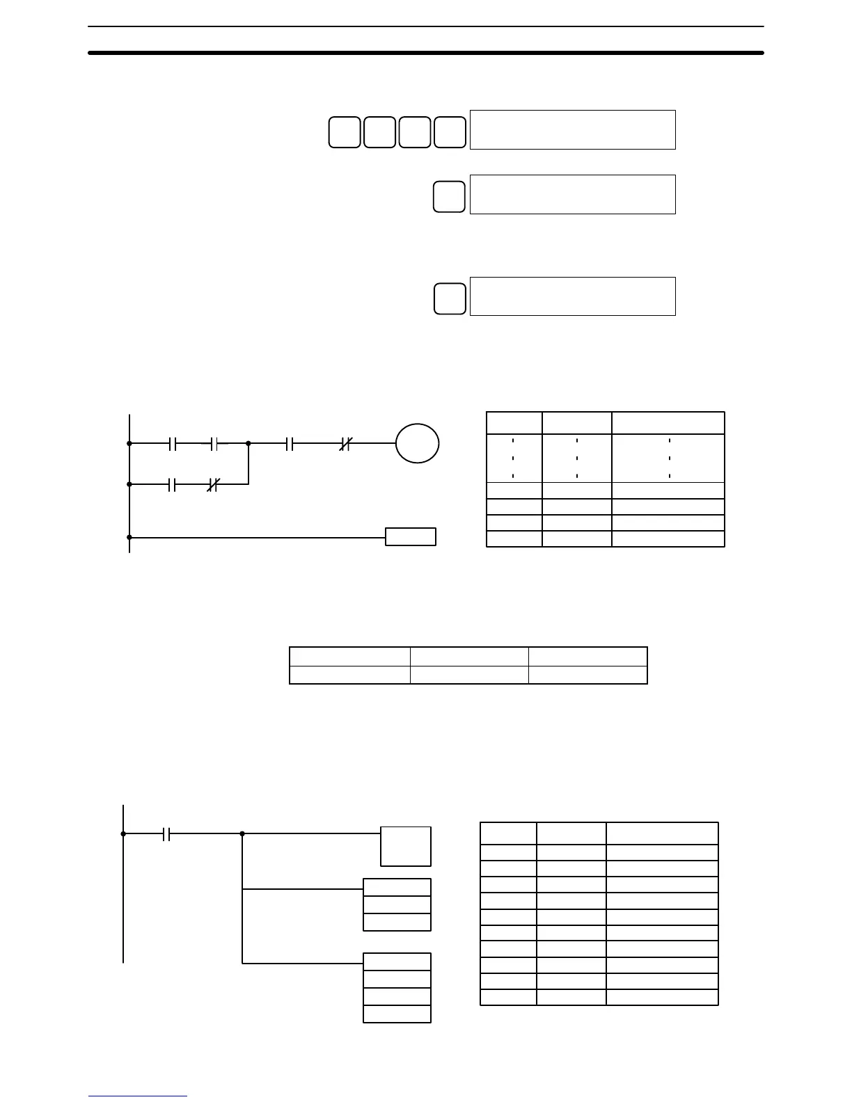
After completing the insertion and deletion procedures, use the Up and Down
Arrow Keys to scroll through the program and verify that it has been changed
correctly, as shown in the following diagram.
00104
00100
0010500101
00201
END(01)
00102
10000
Corrected Program
Address Instruction Operands
00205 AND 00105
00206 AND NOT 00104
00207 OUT 10000
00208 END(01) -
3-6-11 Entering or Editing Programs
This operation is used enter or edit programs. It is possible in PROGRAM mode
only.
RUN MONITOR PROGRAM
No No OK
The same procedure is used to either input a program for the first time or to
change a program that already exists. In either case, the current contents of
Program Memory is overwritten.
The program shown in the following diagram will be entered to demonstrate
this operation.
00002
00200 LD IR 00002
00201 TIM 000
0123
00202 MOV(21)
#0100
LR 10
00203 ADB(50)
#0100
#FFF6
DM 0000
MOV(21)
#0100
LR 10
TIM 000
#0123
12.3 s
ADB(50)
#0100
#FFF6
DM 0000
Address Instruction Operands

Table of Contents

Question and Answer IconNeed help?

Do you have a question about the Sysmac CQM1 and is the answer not in the manual?

Sysmac CQM1 Specifications

General IconGeneral
ManufacturerOmron
Operating Temperature0 to 55°C
Humidity10 to 90% RH (non-condensing)
Power Supply100 to 240 VAC or 24 VDC (depending on model)
Programming LanguageLadder Diagram, Instruction List
Communication PortsRS-232C
ExpansionExpansion I/O units available
Analog I/OAvailable via expansion units
Instruction SetBasic and advanced instructions
Vibration Resistance10 to 57 Hz, 0.075 mm amplitude

Summary

SECTION 1 Introduction

1-1 Overview

Provides an overview of setting up and operating a CQM1 System, referencing relevant manual sections.

1-2 System Configuration

Describes the CQM1 PC as a compact, high-speed system composed of CPU, Power Supply, and I/O Units.

1-3 CQM1 Features

Highlights key advanced features of the CQM1, including built-in I/O, speed, and timers/counters.

SECTION 2 Units and Installation

2-1 CPU Unit

Details the different CPU Unit models, their specifications, components, and functions.

2-2 Power Supply Unit

Explains the available Power Supply Units, their specifications, and selection criteria.

2-3 I/O Units

Describes the types of I/O Units, their specifications, and maximum I/O points.

2-5 Wiring and Connections

Provides basic information on wiring Power Supply, I/O Units, and connecting Peripheral Devices.

2-6 Unit Specifications

Lists detailed specifications for Power Supply Units, CPU Units, and various I/O Units.

SECTION 3 The LSS, SSS, SYSMAC-CPT, and Programming Consoles

3-1 LSS Capabilities

Outlines the capabilities of the Ladder Support Software (LSS) for programming and control.

3-4 Compatible Programming Consoles

Describes the compatible programming consoles and their key functions for system operation.

3-6 Programming Console Operations

Details various operations performable via the Programming Console, such as monitoring and data modification.

SECTION 4 Troubleshooting

4-1 Introduction

Introduces PC errors, categorizing them into Program Input, Programming, User-defined, and Operating errors.

4-3 Programming Errors

Details syntax errors detected during program checks, including types, displays, and explanations.

4-5 Operating Errors

Lists and explains non-fatal and fatal errors that occur during PC operation.

4-6 Troubleshooting Flowcharts

Provides flowcharts to systematically diagnose and resolve hardware and software errors.

Appendix A Standard Models

CPU Units

Lists standard CQM1 CPU Unit models with their appearance, communications, memory, and I/O capacity.

Input Units

Details standard DC and AC Input Units, including model numbers and specifications.

Output Units

Lists standard Contact, Transistor, and Triac Output Units with their specifications.

Appendix B Battery Service Life

Appendix C SYSMAC-CPT Precautions

I/O Table Displays

Lists precautions for using the SYSMAC-CPT Support Software with the CQM1, including I/O table and ladder program displays.

Creating Ladder Programs

Lists precautions for using the SYSMAC-CPT Support Software with the CQM1, including I/O table and ladder program displays.

Glossary

Index