36
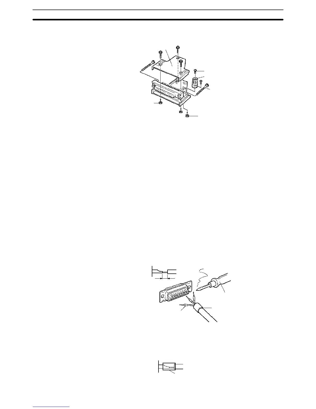
Finally, assemble the socket and connector cover as shown below.
Connector cover
Small screws (3)
Small screws (2)
Socket
Nuts (3)
Nuts (2)
Connector lock screw
Cable clamp
2-5-7 Cable Preparation (Pulse Output and ABS Interface)
Dedicated ports are required for the pulse I/O (CQM1-CPU43-EV1 only) and
ABS interface (CQM1-CPU44-EV1 only) functions. Follow the procedure
explained here to prepare cable for these ports.
Use the following products or equivalents for the connector on the cable side.
Socket: XM2D-1501 (OMRON)
Hood: XM2S-1511 (OMRON)
Cable Use shielded twisted-pair wire for the cable.
Note For details on pin arrangement and the internal circuitry of connectors at the
CQM1 side, refer to the sections on CQM1-CPU43-EV1 and
CQM1-CPU44-EV1 CPU Units in this manual.
Wiring and Assembly The following illustrations show the procedure for wiring and assembly of the
connectors. First pass the signal wires through heat-contraction tubes and sol-
der them to the socket pins.
1 mm
Soldering iron
Fold back the shield.
Heat-contraction tube
Inner diameter: 1.5 mm, l = 10
After soldering all of the necessary pins, slide the heat-contraction tubes over
the soldered areas of the respective wires. Then shrink the tubes by heating
them with a jet of hot air.
Heat-contraction tube
Applicable Connectors
(Cable Side)
Wiring and Connections
Section 2-5