24
2-4 PC Assembly and Installation
This section describes how to assemble the Units that make up the CQM1 PC
and install the PC on a DIN Track.
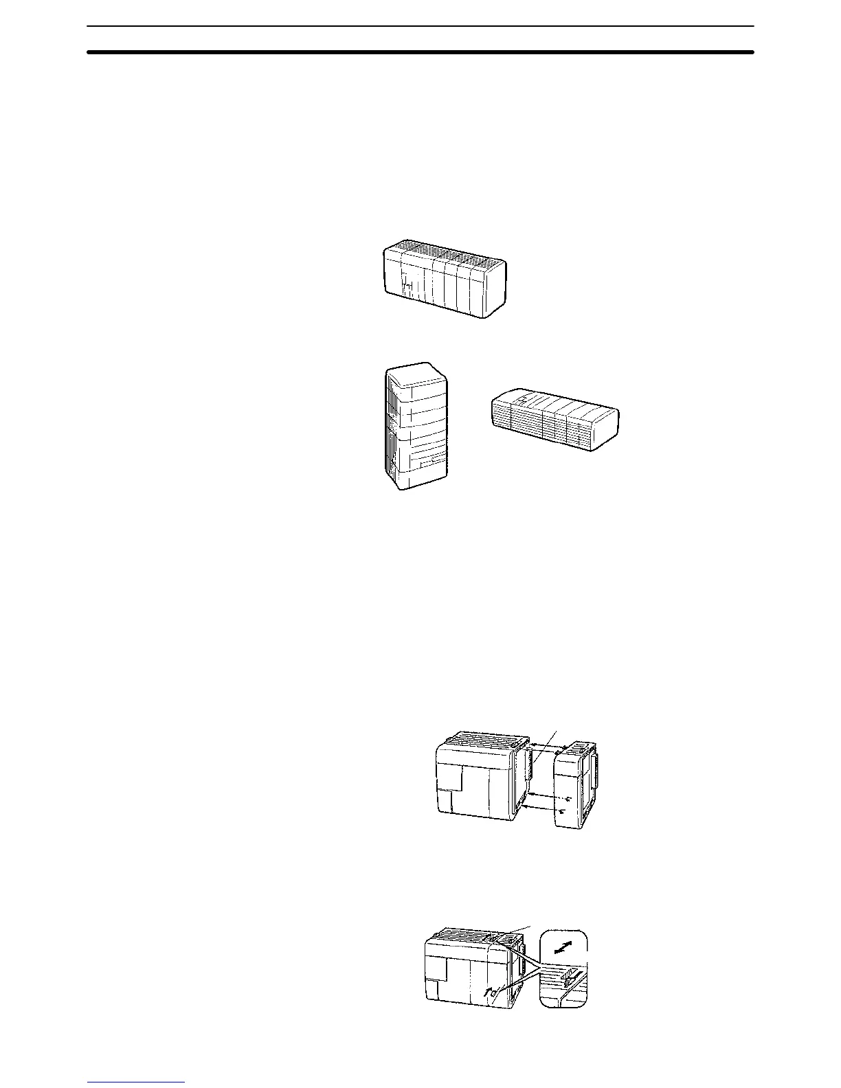
When installing the CQM1 in the control panel, always mount the Units so that
the ventilation openings are facing up. Also, there must be at least a 20-mm
space both above and below the PC.
Correct
Wrong
Wrong
2-4-1 Connecting PC Components
The Units that make up a CQM1 PC can be connected simply by pressing the
Units together and sliding the locking tabs towards the back of the Units. The
End Cover is connected in the same way to the Unit on the far right side of the
PC. Follow the procedure listed below to connect PC components.
Always turn off the CQM1 when connecting or disconnecting Units. Replace
Units only after shutting down the CQM1 system.
1, 2, 3...
1. The following diagram shows the connection of two Units that make up a
CQM1 PC. Join the Units so that the connectors fit exactly.
Connector
2. The yellow locking tabs at the top and bottom of each Unit lock the Units
together. Slide these locking tabs towards the back of the Units as shown
below.
Lock
Release
Slider
PC Orientation
PC Assembly and Installation
Section 2-4