116
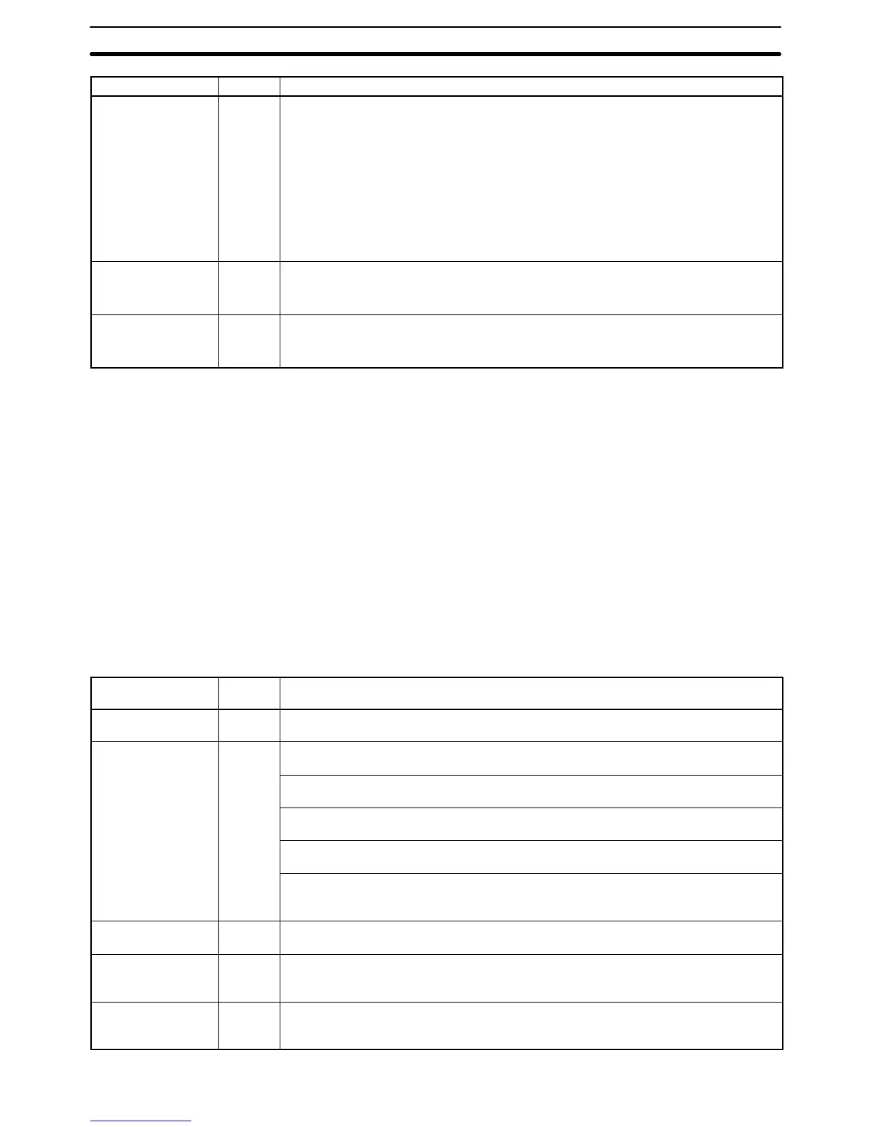
Message Meaning and appropriate responseFAL No.
SYS FAIL FAL**
(see note)
9B An error has been detected in the PC Setup. Check flags AR 2400 to AR 2402, and
correct as directed.
AR 2400 ON: An incorrect setting was detected in the PC Setup (DM 6600 to DM
6614) when power was turned on. Correct the settings in PROGRAM Mode and turn
on the power again.
AR 2401 ON: An incorrect setting was detected in the PC Setup (DM 6615 to DM
6644) when switching to RUN Mode. Correct the settings in PROGRAM Mode and
switch to RUN Mode again.
AR 2402 ON: An incorrect setting was detected in the PC Setup (DM 6645 to DM
6655) during operation. Correct the settings and clear the error.
SCAN TIME OVER F8 Watchdog timer has exceeded 100 ms. (SR 25309 will be ON.)
This indicates that the program cycle time is longer than recommended. Reduce cycle
time if possible.
BATT LOW F7 Backup battery is missing or its voltage has dropped. (SR 25308 will be ON.)
Check the battery and replace if necessary. Check the PC Setup (DM 6655) to see
whether a low battery will be detected.
Note ** is 01 to 99, 9D, 9C, or 9B.
Communication Errors If an error occurs in communications through the peripheral port or RS-232C
port the corresponding indicator (COM1 or COM2) will stop flashing. Check the
connecting cables as well as the programs in the PC and host computer.
Reset the communications ports with the Port Reset Bits, SR 25208 and
SR 25209.
Output Inhibit When the OUT INH indicator is lit, the Output Inhibit Bit (SR 25215) is ON and all
outputs from the CPU Unit will be turned off. If it is not necessary to have all out-
puts off, turn OFF SR 25215.
4-5-2 Fatal Errors
PC operation and program execution will stop and all outputs from the PC will be
turned OFF when any of these errors have occurred.
All CPU Unit indicators will be OFF for the power interruption error. For all other
fatal operating errors, the POWER and ERR/ALM indicators will be lit. The RUN
indicator will be OFF.
Message FALS
No.
Meaning and appropriate response
Power interruption
(no message)
None Power has been interrupted for at least 10 ms. Check power supply voltage and power
lines. Try to power-up again.
MEMORY ERR F1
AR 1611 ON: A checksum error has occurred in the PC Setup (DM 6600 to DM 6655).
Initialize all of the PC Setup and reinput.
AR 1612 ON: A checksum error has occurred in the program, indicating an incorrect
instruction. Check the program and correct any errors detected.
AR 1613 ON: A checksum error has occurred in an expansion instruction’s data.
Initialize all of the expansion instruction settings and reinput.
AR 1614 ON: Memory Cassette was installed or removed with the power on. Turn the
power off, install the Memory Cassette, and turn the power on again.
AR 1615 ON: The Memory Cassette contents could not be read at start-up. Check
flags AR 1412 to AR 1415 to determine the problem, correct it, and turn on the power
again.
NO END INST F0 END(01) is not written anywhere in program. Write END(01) at the final address of the
program.
I/O BUS ERR C0 An error has occurred during data transfer between the CPU Unit and an I/O Unit.
Determine the location of the problem using flags AR 2408 to AR 2415, turn the power
off, check for loose I/O Units or end covers, and turn on the power again.
I/O UNIT OVER E1 The number of I/O words on the installed I/O Units exceeds the maximum. Turn off the
power, rearrange the system to reduce the number of I/O words, and turn on the
power again.
Operating Errors
Section 4-5