EasyManua.ls Logo

Sysmac CQM1 User Manual

Default Icon
159 pages
To Next Page IconTo Next Page
To Previous Page IconTo Previous Page
Page #102 background imageLoading...
Page #102 background image
3-6SectionProgramming Console Operations
90
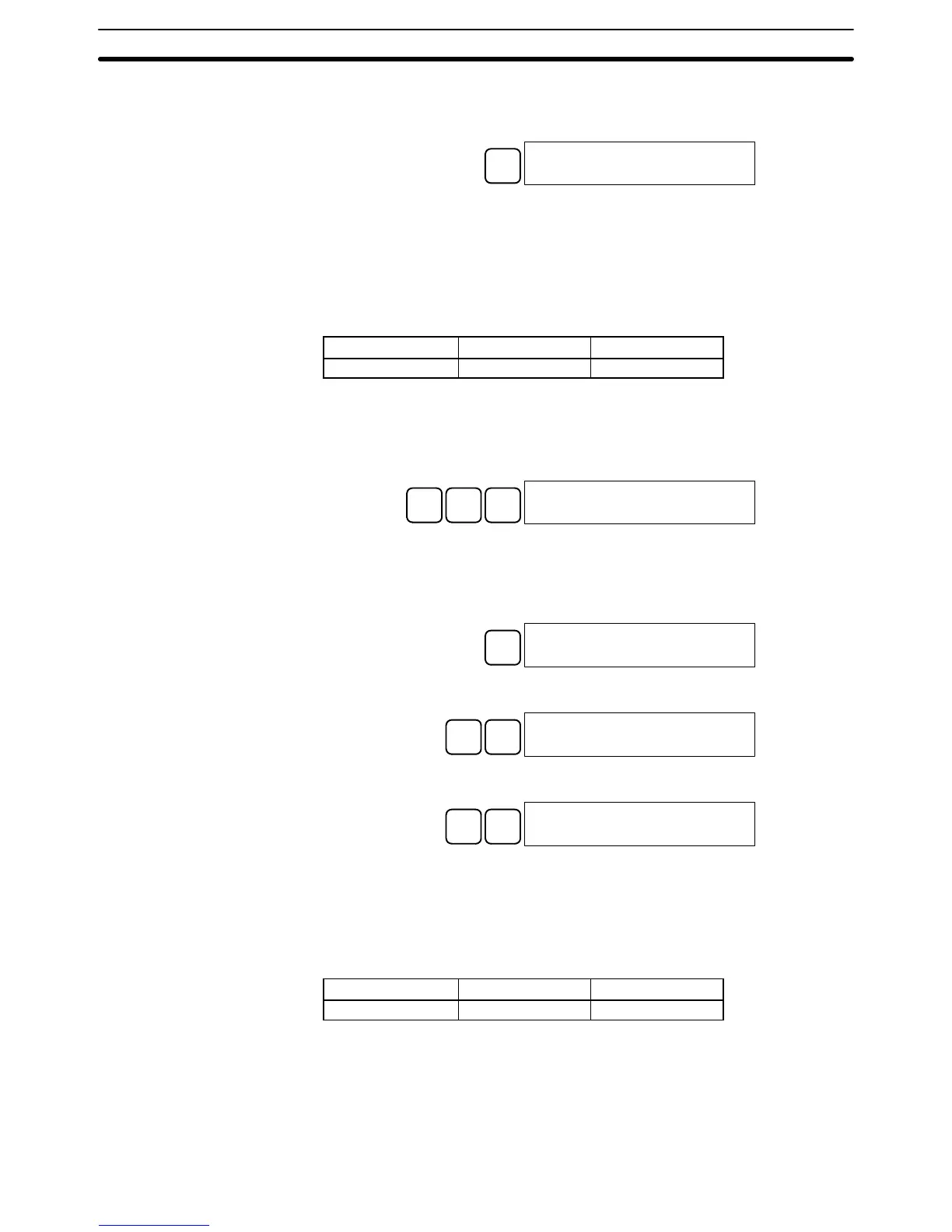
4. When the desired instruction is displayed, press the WRITE Key to change
the function code assignment. The following display will appear if the
selected instruction has not been assigned to another function code.
WRITE
INST TBL READ
FUN18:HKY
Note It is not possible to change to an instruction which is already assigned
to a different function code.
3-6-6 Reading and Changing the Clock
This operation is used to read and change the clock in PCs that have a Memory
Cassette equipped with a clock. It is possible to read the clock in any mode, but
the clock can be changed in MONITOR or PROGRAM mode only.
RUN MONITOR PROGRAM
OK (reading only) OK OK
Reading the Clock Follow the procedure below to read the clock.
1, 2, 3...
1. Bring up the initial display.
2. Press the FUN, SHIFT, and then the MONTR Key. The current clock setting
will be displayed.
FUN
SHIFT
MONTR
TIM 93-03-17
10:56:36 TUE(2)
Changing the Clock Follow the procedure below to change the clock setting. The clock setting cannot
be changed in RUN mode.
1, 2, 3...
1. Follow the procedure above to display the current clock setting.
2. Press the CHG Key. The following display will appear.
CHG
TIM CHG?~3-03-17
10:57:00 TUE(2)
3. Use the Up and Down Arrow Keys to move the cursor to the unit that will be
changed. In this case, the day of the week is being changed.
TIM CHG?93-03-17
10:58:00 TUE(~)
4. Input the new value and press the WRITE Key. The new setting will appear
on the display.
D
3
WRITE
TIM 93-03-17
10:58:30 WED(3)
Note The days of the week correspond to the following numbers: Sun.=0,
Mon.=1, Tue.=2, Wed.=3, Thu.=4, Fri.=5, and Sat.=6.
3-6-7 Setting and Reading a Program Memory Address
This operation is used to display the specified program memory address and is
possible in any mode.
RUN MONITOR PROGRAM
OK OK OK
When inputting a program for the first time, it is generally written to Program
Memory starting from address 000. Because this address appears when the
display is cleared, it is not necessary to specify it.
When inputting a program starting from other than 000 or to read or modify a
program that already exists in memory, the desired address must be desig-
nated.

Table of Contents

Question and Answer IconNeed help?

Do you have a question about the Sysmac CQM1 and is the answer not in the manual?

Sysmac CQM1 Specifications

General IconGeneral
ManufacturerOmron
Operating Temperature0 to 55°C
Humidity10 to 90% RH (non-condensing)
Power Supply100 to 240 VAC or 24 VDC (depending on model)
Programming LanguageLadder Diagram, Instruction List
Communication PortsRS-232C
ExpansionExpansion I/O units available
Analog I/OAvailable via expansion units
Instruction SetBasic and advanced instructions
Vibration Resistance10 to 57 Hz, 0.075 mm amplitude

Summary

SECTION 1 Introduction

1-1 Overview

Provides an overview of setting up and operating a CQM1 System, referencing relevant manual sections.

1-2 System Configuration

Describes the CQM1 PC as a compact, high-speed system composed of CPU, Power Supply, and I/O Units.

1-3 CQM1 Features

Highlights key advanced features of the CQM1, including built-in I/O, speed, and timers/counters.

SECTION 2 Units and Installation

2-1 CPU Unit

Details the different CPU Unit models, their specifications, components, and functions.

2-2 Power Supply Unit

Explains the available Power Supply Units, their specifications, and selection criteria.

2-3 I/O Units

Describes the types of I/O Units, their specifications, and maximum I/O points.

2-5 Wiring and Connections

Provides basic information on wiring Power Supply, I/O Units, and connecting Peripheral Devices.

2-6 Unit Specifications

Lists detailed specifications for Power Supply Units, CPU Units, and various I/O Units.

SECTION 3 The LSS, SSS, SYSMAC-CPT, and Programming Consoles

3-1 LSS Capabilities

Outlines the capabilities of the Ladder Support Software (LSS) for programming and control.

3-4 Compatible Programming Consoles

Describes the compatible programming consoles and their key functions for system operation.

3-6 Programming Console Operations

Details various operations performable via the Programming Console, such as monitoring and data modification.

SECTION 4 Troubleshooting

4-1 Introduction

Introduces PC errors, categorizing them into Program Input, Programming, User-defined, and Operating errors.

4-3 Programming Errors

Details syntax errors detected during program checks, including types, displays, and explanations.

4-5 Operating Errors

Lists and explains non-fatal and fatal errors that occur during PC operation.

4-6 Troubleshooting Flowcharts

Provides flowcharts to systematically diagnose and resolve hardware and software errors.

Appendix A Standard Models

CPU Units

Lists standard CQM1 CPU Unit models with their appearance, communications, memory, and I/O capacity.

Input Units

Details standard DC and AC Input Units, including model numbers and specifications.

Output Units

Lists standard Contact, Transistor, and Triac Output Units with their specifications.

Appendix B Battery Service Life

Appendix C SYSMAC-CPT Precautions

I/O Table Displays

Lists precautions for using the SYSMAC-CPT Support Software with the CQM1, including I/O table and ladder program displays.

Creating Ladder Programs

Lists precautions for using the SYSMAC-CPT Support Software with the CQM1, including I/O table and ladder program displays.

Glossary

Index