51
2-6-5 24-VDC Inputs (Built into CPU Unit)
Item CQM1-CPU11-E/21-E/41-EV1/42-EV1/43-EV1/44-EV1
Input Voltage 24 VDC
+10%
/
–15%
Input Impedance IN4 and IN5: 2.2 kΩ; other inputs: 3.9 kΩ
Input Current IN4 and IN5: 10 mA typical; other inputs: 6 mA typical (at 24 VDC)
ON Voltage 14.4 VDC min.
OFF Voltage 5.0 VDC max.
ON Delay Default: 8 ms max. (can be set between 1 and 128 ms in PC Setup; see note)
OFF Delay Default: 8 ms max. (can be set between 1 and 128 ms in PC Setup; see note)
No. of Inputs 16 points (16 inputs/common, 1 circuits)
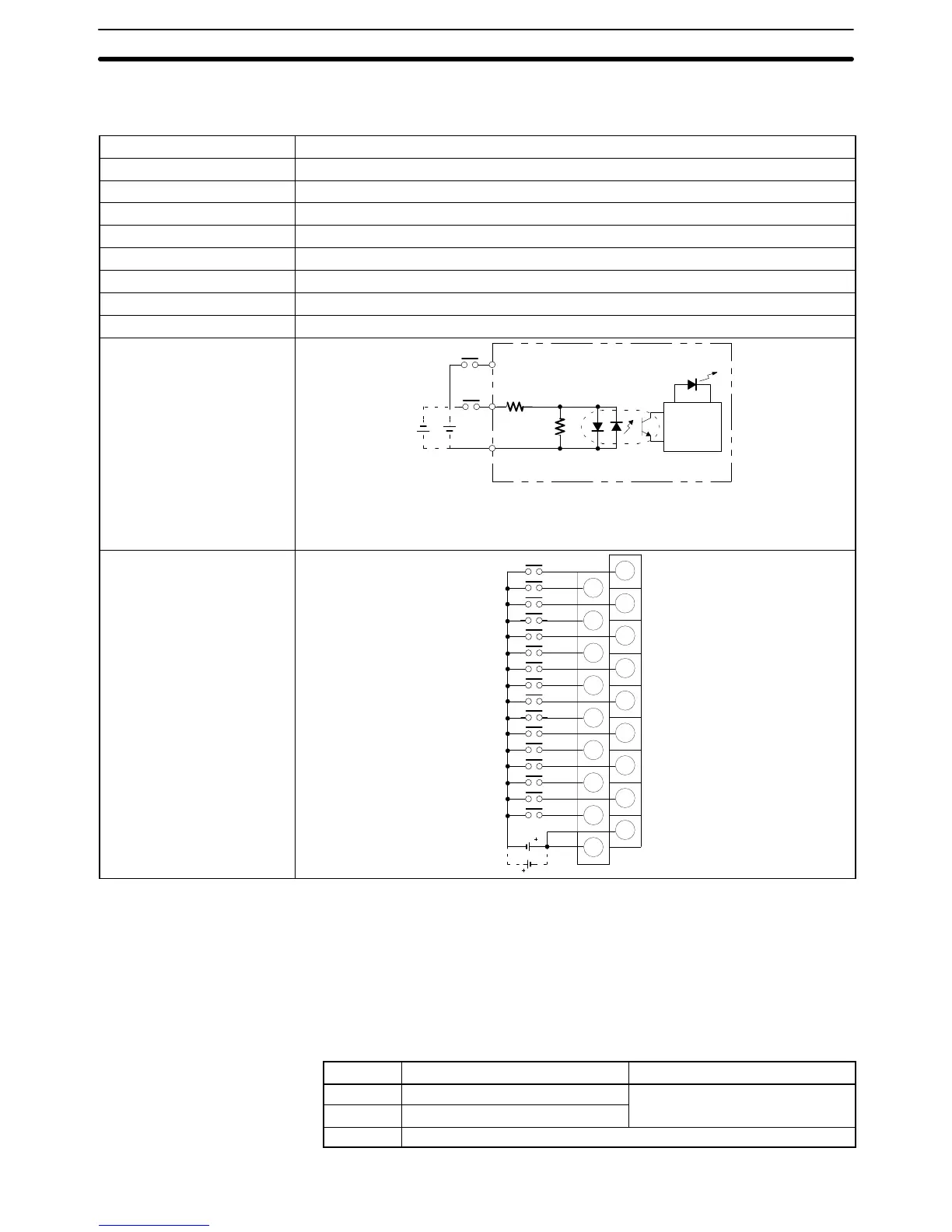
Circuit Configuration
IN0
to
IN15
COM
3.9 kΩ
(2.2 kΩ)
Input
LED
Internal
Circuits
560 Ω
Note Figures in parentheses are for IN4 and IN5.
The input power supply polarity may be con-
nected in either direction.
Terminal Connections
B0
0
1
A0
B1
2
3
A1
B2
4
5
A2
B3
6
7
A3
B4
8
9
A4
B5
10
11
A5
B6
12
13
A6
B7
14
15
A7
B8
COM
A8
COM
–
–
Note IN0 through IN3 can be set for use as input interrupts in the PC Setup. The ON
and OFF delays for input interrupts are fixed at 0.1 ms max. and 0.5 ms max.,
respectively. IN4 through IN6 can be set for use as high-speed counter inter-
rupts. The delays for high-speed counter interrupts are shown in the following
table.
Input Increment input mode Differential phase mode
IN4 (A) 5 KHz
2.5 KHz
IN5 (B) Normal input
IN6 (Z) ON: 100 ms min. required; OFF delay: 500 ms min. required
Unit Specifications
Section 2-6