35
The following circuit reduces the surge current by employing a current-limiting
resistor.
LOUT
COM
+
R
2-5-6 Cable Preparation (Connector Type)
Prepare the cable for connector-type I/O Units as explained below.
Connector type Model (by Fujitsu) Set (from OMRON)
Soldered Socket: FCN-361J040-AU
Connector cover: FCN-360C040-J2
C500-CE404
Crimp Housing: FCN-363J040
Contact: FCN-363J-AU
Connector cover: FCN-360C040-J2
C500-CE405
Pressure welded FCN-367J040-AU/F C500-CE403
A soldered-type socket and connector cover are provided with each I/O Unit.
Recommended Wire Use AWG26 to 24 (0.2 to 0.13 mm
2
) wire for connecting to all of the connector
pins.
Note For details on pin arrangement and the internal circuitry of connectors at the
CQM1 side, refer to the sections on DC Input Units (32 points) and Transistor
Output Units (32 points) in this manual.
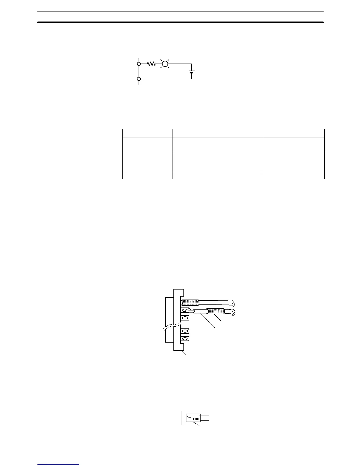
Wiring and Assembly The following illustrations show the procedure for wiring and assembly of solder-
type connectors. First pass the electrical wires through heat-contraction tubes
and solder them to the socket pins.
Heat-contraction tube
Electrical wire
Connector
After soldering all of the necessary pins, slide the heat-contraction tubes over
the soldered areas of the respective wires. Then shrink the tubes by heating
them with a jet of hot air.
Heat-contraction tube
Recommended Connectors
(Cable Side)
Wiring and Connections
Section 2-5