33
The value of I
OFF
is different for different Units, and is 1.3 mA for all Units for
which the OFF current is not listed in the Unit specifications.
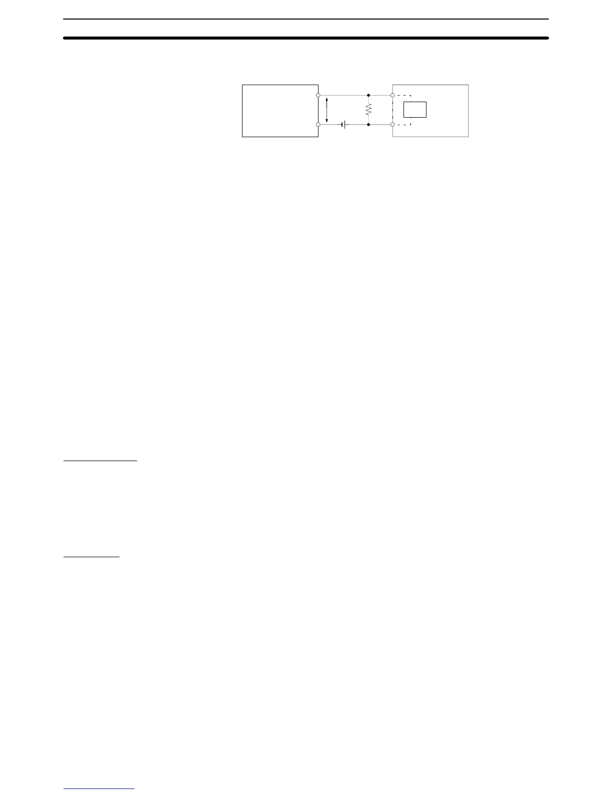
V
R
V
CC
RR
IN
2-wire sensor
DC Input
Unit
V
CC
: Power supply voltage
V
ON
: PC’s ON voltage
I
ON
: PC’s ON current
I
OFF
: PC’s OFF current
R
IN
: PC’s input impedance
V
R
: Sensor’s output residual voltage
I
OUT
: Sensor’s control output (load current)
I
leak
: Sensor’s leakage current
R: Bleeder resistor
2-5-5 Compliance with EC Directives
The following precautions must be abided by when installing CQM1-series PCs
to meet EC Directives.
1, 2, 3...
1. CQM1-series PCs are classified as open-structure devices and must be
installed inside a control panel.
2. Use reinforced insulation or double insulation on the DC power supply con-
nected to DC Power Supply Unit and DC I/O Units.
3. CQM1-series PCs that meet EC Directives meet the common emission
standard (EN50081-2) of the EMC Directives as individual products. When
assembled into machinery, however, the noise generated by switching relay
outputs can fail to meet the standard. When noise is excessive, surge killers
must be installed or other measures must be taken outside of the PC. The
measures required to meet the standard will vary with the load being driven,
wiring, the configuration of the machinery, etc.
The following examples show means of reducing noise. These means will
only reduce the amount of noise and will not eliminate noise. They are pro-
vided here as examples only.
Requirement
The following conditions can be used to determine if measures to reduce noise
are necessary. Refer to the EN50081-2 Standard for details.
• If the loads of the devices into which the PC is built are switched less than 5
times a minute, then no measures need to be taken.
• If the loads of the devices into which the PC is built are switched 5 times or
more a minute, then measures need to be taken.
Examples
Connect a surge suppressor or diode in parallel with the load, as shown in the
following diagrams, when switching inductive loads.
CR Method (AC or DC)
The reset time will be increased if the load is a relay, solenoid, or similar device.
Connect the CR between the load connections for 24-V and 48-V power supply
voltages and between the contact connections for 100 to 200-V power supply
voltages.
The capacitor and resistors can be based on the following guidelines.
C: 0.5 to 1 µF for each amp of contact current
R: 0.5 to 1 Ω for each volt of contact voltage.
You will need to adjust the above values depending on the characteristics of the
load, relay, etc., based on the discharge suppression of the capacitor when the
contacts are open and the current control effect of the resistor the next time the
circuit is closed.
Inductive Load Surge
Suppressor
Wiring and Connections
Section 2-5