32
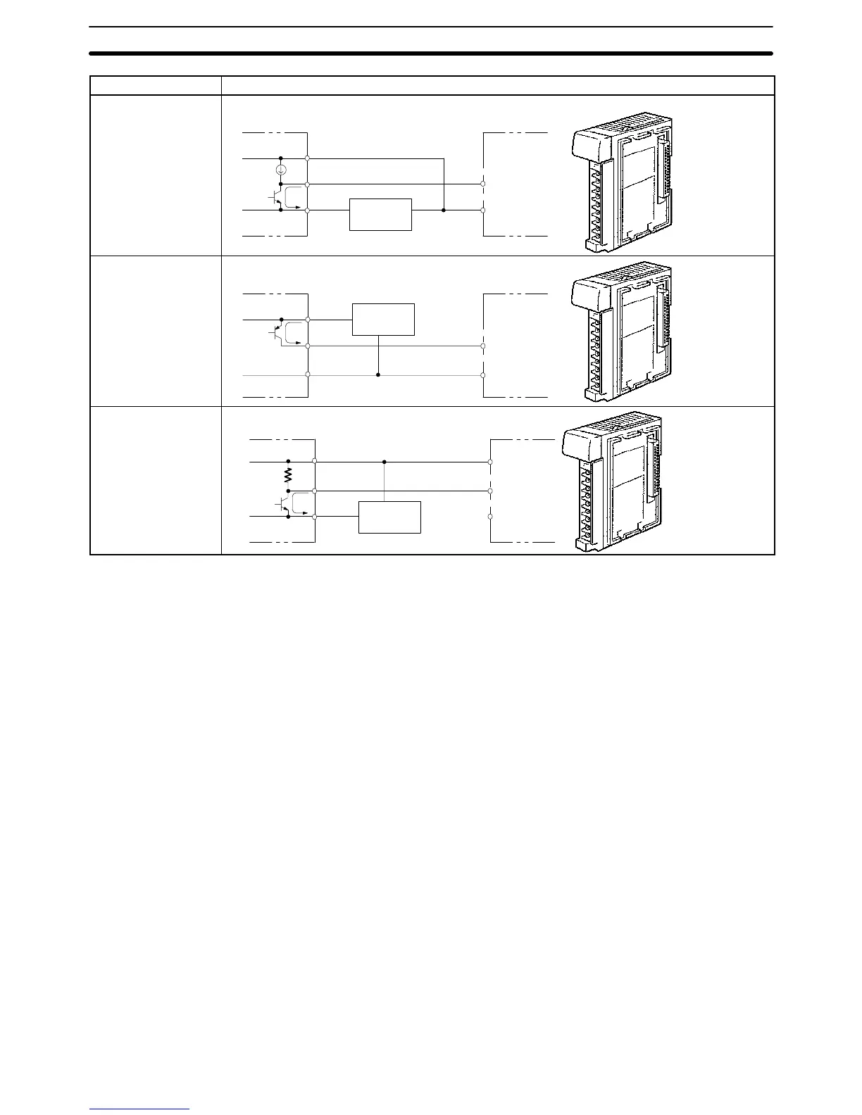
Device Circuit Diagram
NPN current output
Sensor power
supply
0 V
+
IN
COM(+)
Constant current
circuit
Output
Use the same power supply for
the input and sensor.
+
PNP current output
Sensor power
supply
COM(–)
0 V
IN
+
Output
Voltage output
Sensor power
supply
IN
COM (+)
0 V
Output
The following conditions must be met when using a 2-wire DC sensor input from
a 12-/24-VDC input device. Malfunctions will occur if these connections are not
met.
1, 2, 3...
1. The relationship between the PC’s ON voltage and the sensor’s residual
voltage must be as follows:
V
ON
≤ V
CC
– V
R
2. The relationship between the PC’s ON current and the sensor’s control out-
put (load current) must be as follows:
I
OUT
(min.) x I
ON
x I
OUT
(max.)
Where, I
ON
= (V
CC
– V
R
– 1.5 (residual voltage in PC))/R
IN
If I
ON
is less than I
OUT
(min.), connect a bleeder resistor, R. The resistance
constant of the bleeder resistor can be calculated as follows:
R x (V
CC
– V
R
)/(I
OUT
(min.) – I
ON
)
Power W y (V
CC
– V
R
)
2
/R x 4 (tolerance)
3. The relationship between the PC’s OFF current and the sensor’s residual
current must be as follows:
I
OFF
y I
leak
Refer to
Leakage Current (24 VDC)
earlier in this section for details.
Precautions in Connecting
2-wire DC Sensors
Wiring and Connections
Section 2-5