8
2-1-2 DIP Switch
The DIP switch is located under a cover on the front of the CPU Unit as shown in
2-1-1 CPU Unit Components
. The setting of these switches is described in the
following table.
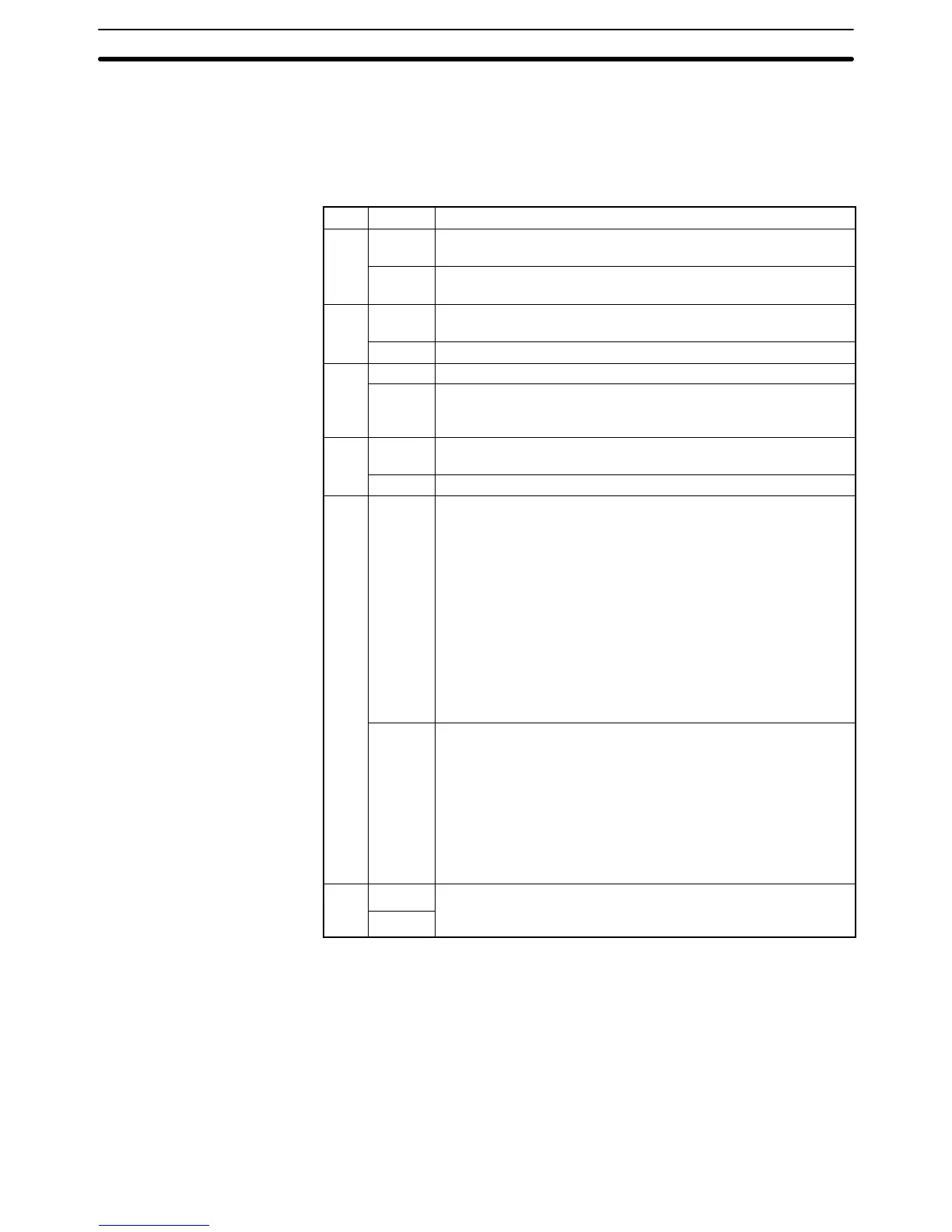
Pin Setting Function
1
ON Program Memory and read-only DM (DM 6144 to DM 6655) data
cannot be overwritten from a Peripheral Device.
OFF Program Memory and read-only DM (DM 6144 to DM 6655) data
can be overwritten from a Peripheral Device.
2
ON Auto-boot enabled. The contents of Memory Cassette will be
transferred to the CPU Unit automatically at start-up.
OFF Auto-boot disabled.
3
ON Programming Console messages will be displayed in English.
OFF Programming Console messages will be displayed in the lan-
guage stored in system ROM. (Messages will be displayed in
Japanese with the Japanese version of system ROM.)
4
ON Expansion instructions set by user. Normally ON when using a
host computer for programming/monitoring.
OFF Expansion instructions set to defaults.
5
ON Standard communications parameters (see note 2) will be set for
the following serial communications ports.
• Built-in RS-232C port
• Peripheral port (only when a CQM1-CIF01/-CIF02 Cable is con-
nected. Does not apply to Programming Console.)
Note 1. Standard communications parameters are as follows:
Serial communications mode: Host Link or peripheral
bus; start bits: 1; data length: 7 bits; parity: even; stop
bits: 2; baud rate: 9,600 bps
2. The CX-Programmer running on a personal computer
can be connected to the peripheral port via the peripher-
al bus using the above standard communications pa-
rameters.
OFF The communications parameters for the following serial
communications ports will be set in PC Setup as follows:
• Built-in RS-232C port: DM 6645 and DM 6646
• Peripheral port: DM 6650 and DM 6651
Note When the CX-Programmer is connected to the peripheral
port with the peripheral bus, either set bits 00 to 03 of DM
6650 to 0 Hex (for standard parameters), or set bits 12 to 15
of DM 6650 to 0 Hex and bits 00 to 03 of DM 6650 to 1 Hex
(for Host Link or peripheral bus) separately.
6
ON
The setting of pin 6 determines the ON/OFF status of AR 0712. If
p
be OFF. (See note 3.)
Note 1. All DIP switch pins except pin 3 are turned OFF at the factory.
2. The above settings apply to CPU Units manufactured from July 1995 (lot
number jj75 for July 1995). For CPU Units manufactured before July
1995 (lot number jj65 for June 1995), only 1 stop bit will be set and the
baud rate will be 2,400 bps.
3. Pin 6 can be used to control the status of AR 0712 in memory to provide
optional control of program execution.
CPU Unit Section 2-1