9
2-1-3 Indicators
CPU Unit indicators provide visual information on the general operation of the
PC. Although not substitutes for proper error programming using the flags and
other error indicators provided in the data areas of memory, these indicators pro-
vide ready confirmation of proper operation. CPU Unit indicators are shown
below and are described in the following table.
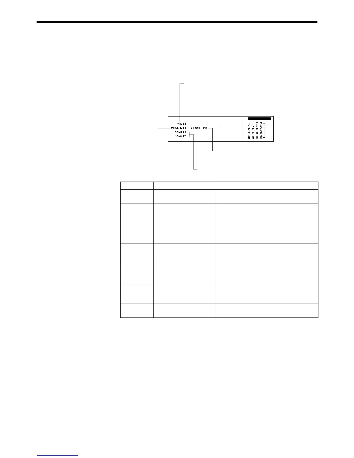
Input Status
Indicators
RUN indicator (Green)
Error/alarm
indicator (Red)
Peripheral port (COM1) (Orange)
RS-232C port (COM2) (Orange)
Output inhibited indicator (Orange)
CPU21-E
The indicator here depends on the Unit:
CPU43-EV1: Pulse I/O
CPU44-EV1: ABS interface
Indicator Name Function
RUN RUN indicator Lights when the CPU Unit is operating
normally.
ERR/ALM Error/Alarm indicator Flashes when there is a non-fatal error.
The CPU Unit will continue operating.
Lit when there is a fatal error. When this
indicator lights, the RUN indicator will go
off, CPU Unit operation will be stopped,
and all outputs will be turned OFF.
COM1 Peripheral port indicator Flashes then the CPU Unit is
communicating with another device via
the peripheral port.
COM2 RS-232C port indicator
Flashes when the CPU Unit is
communicating with another device via
the RS-232C port. (CQM1-CPU21-E only)
OUT INH Output inhibited indicator Lights when the Output OFF Bit, SR
25215, is turned ON. All PC outputs will
be turned OFF.
0, 1, 2 . . . Input status indicators
Indicate the ON and OFF status of input
bits in IR 000.
CPU Unit Section 2-1