!
!
!
!
28
Caution Be sure that the DC power supply voltage remains within the allowed fluctuation
range of 20 to 28 VDC.
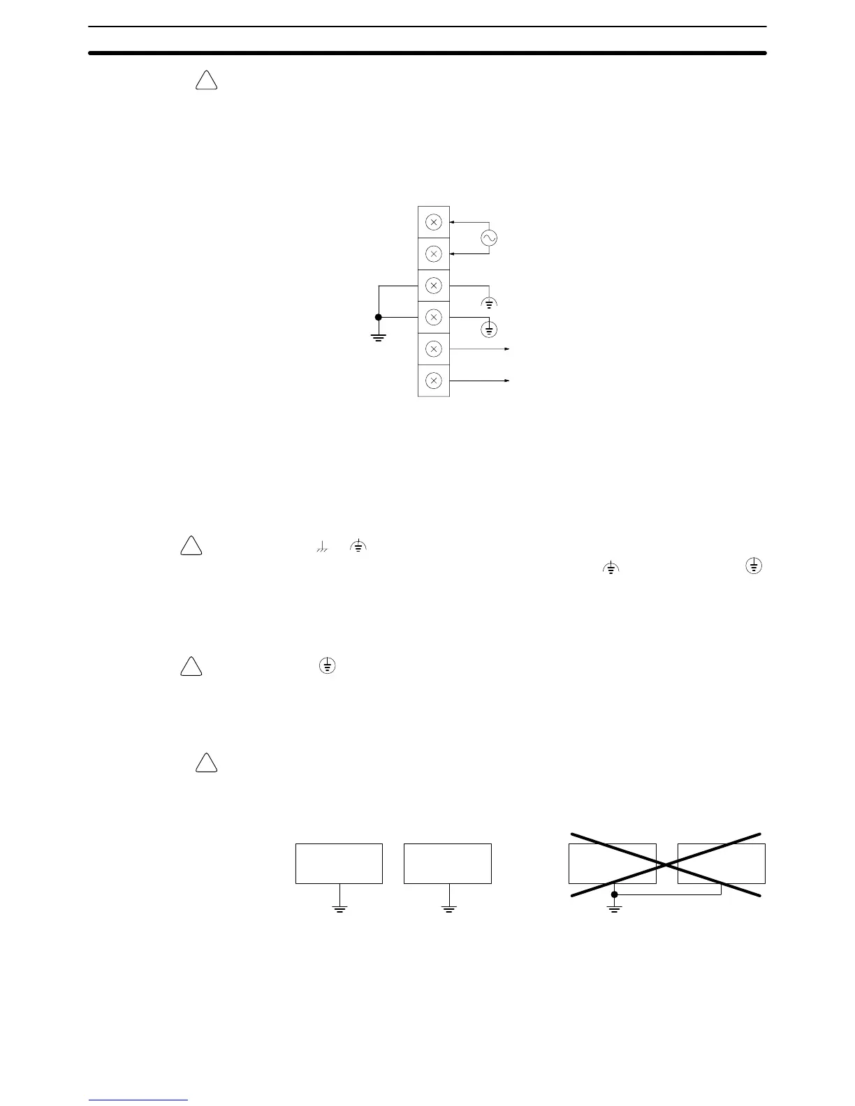
Terminal Block The following diagram shows the terminal blocks for the DC Power Supply Unit.
CQM1-PD026
DC
input
Provide a 24-VDC
power supply.
NC
NC
Noise filter neutral terminal
Protective earth terminal
The wire used should be at least 2 mm
2
. Provide the grounding point as close to
the CQM1 PC as possible.
Note To satisfy the EC directives (low-voltage directive), provide reinforced insulation
or double insulation for the power supply.
WARNING LG ( or ):
Noise filter neutral terminal. Short-circuit the LG (
) terminal and GR ( )
terminals using the attached short-circuit bar and ground them at a resistance of
less than 100 Ω to reduce noise and prevent electric shock.
WARNING GR ( ):
Protective earth terminal. Connect to a separate ground wire of at least 2 mm
2
to
ground the terminal at a resistance of less than 100 Ω to prevent electric shock.
Caution Avoid sharing the grounding wire with other equipment or attaching to the beam
of a building, otherwise it may cause an adverse effect.
CQM1
Other
equipment
CQM1
Other
equipment
Correct Incorrect
2-5-3 Wiring Precautions for Ground Wires
Wire the grounding wires according to the diagram shown below. The CQM1 PC
with the lot number jjZ5 manufactured in December 1995 and later is pro-
vided with the LG-GR short-circuit bar and the DIN-track cable.
Wiring and Connections
Section 2-5