49 49
Z-10
IWZ02-616201E
WZ02-6161E
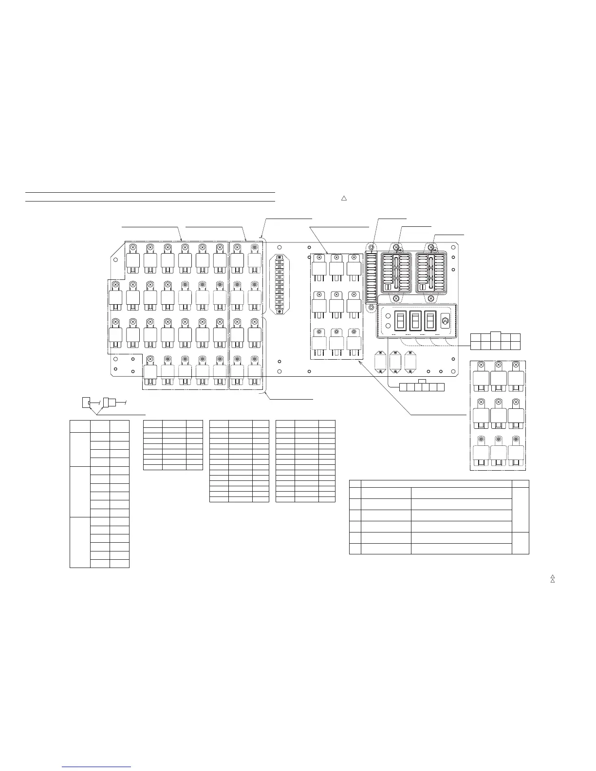
Electric Parts Location Diagram (Upper)
2. Relay assy (inside cab)
Z-10
Z-10
1
343-546-81500
0
343-546-81501
Applicable serial No. : FE0760--
A
Number
of poles
Spare
c
b
Name
Code
a
d
Emergency
accelerator
Suspension
emergency free
Emergency
transmission
DPF emergency
cancel
Spare
SpareSpareSpareSpareSpareSpare
SpareSpareSpareSpareSpare
SpareSpareSpare
(c)
(c)
(d)
(d)
(b)(a)
(a) (b)
(d)(c)(b)(a)
Up: During emergency transmission operating
Down: Normal state
Up: During emergency accelerator operating
Down: Normal state
Up: During DPF emergency cancel operating
Down: Normal state
Up: During suspension emergency free operating
Down: Normal state
Fuse
box
Crane section relay
Fuse connector No.
Fuse box (L)
Fuse box (M)
Fuse box (R)
c-contact
(Combination type relay)
a-contact
(Normal open type relay)
b-contact
(Normal close type relay)
Carrier section relay
Vehicle relay
NoteFuse code
Fuse box (R)
Location
Spare
Spare
Spare
NoteFuse code
Fuse box (M)
Location
Spare
Spare
Spare
NoteFuse code
Fuse box (L)
Location
(f)
(e)
e
4th-Top boom section
emergency telescoping
Push: During emergency operating
Release: Normal state
f
2nd-3rd boom section
emergency telescoping
Push: During emergency operating
Release: Normal state
SpareSpareSpare
SpareSpareSpare
CN869
CN876
CN1612
CN1613
4-F(8.0)
4-F(CN_A)
CN1611
4-M(8.0)
CN1610
4-M(CN_A)
4-M
6-M
2-F
CN No.
4-F
6-F
2-M
6-M
2-F
4-F
6-F
F M
CN877
CN878
CN879
CN868
CN870
CN871
CN872
CN873
2-M
4-M
CN874
CN875
CN564
CN No.
A
B
C
D
E
G
H
F
R48R9R36R24R7R6R58R26R1
RA94RA31RA26RA14
RB5RA6RA5RA4RA3RA2RA1
ON
OFF
ON
OFF
ON
OFF
C
D
F
B
A
H
I
J
X
EK
Z
Y
G
C
D
F
B
A
H
I
J
X
EK
Z
Y
G
CN564
B
R
B
R
BB
R R
M
(L)
(M)
(R)
Y
X
K
J
I
H
G
F
E
D
C
B
A
Z
5A
10A
15A
15A
15A
10A
10A
10A
10A
15A
10A
15A
5A
5A
Y
X
K
J
I
H
G
F
E
D
C
B
A
Z
5A
10A
15A
15A
15A
10A
10A
10A
10A
15A
10A
15A
5A
5A
H
G
F
E
D
C
B
A
10A
5A
5A
5A
5A
10A
5A
10A
R92
(f) (e)(f) (f)
CN503
R WW B
(e)
B
(e)
R
M
CN503
R60
R43RC7
RC3RC2RC1
R60
R43RC7
RC3RC2RC1
△
A