2.8 Clearance check at sides
of the boom bottom
(Section [2] shown in Figure 1)
• 2nd, 3rd, 5th, and top boom sections:
Check that the minimum clearance in the rear end
lateral side (dimension D) is 5 mm (0.2 in) or
more.
• 4th boom section:
Check that the minimum clearance in the rear end
lateral side (dimension D) is 8 mm (0.31 in) or
more.
[NOTICE]
If the dimension D is not satisfied, go back to the
step "2.5 Clearance adjustment at upper part of
boom head" and adjust again thereafter.
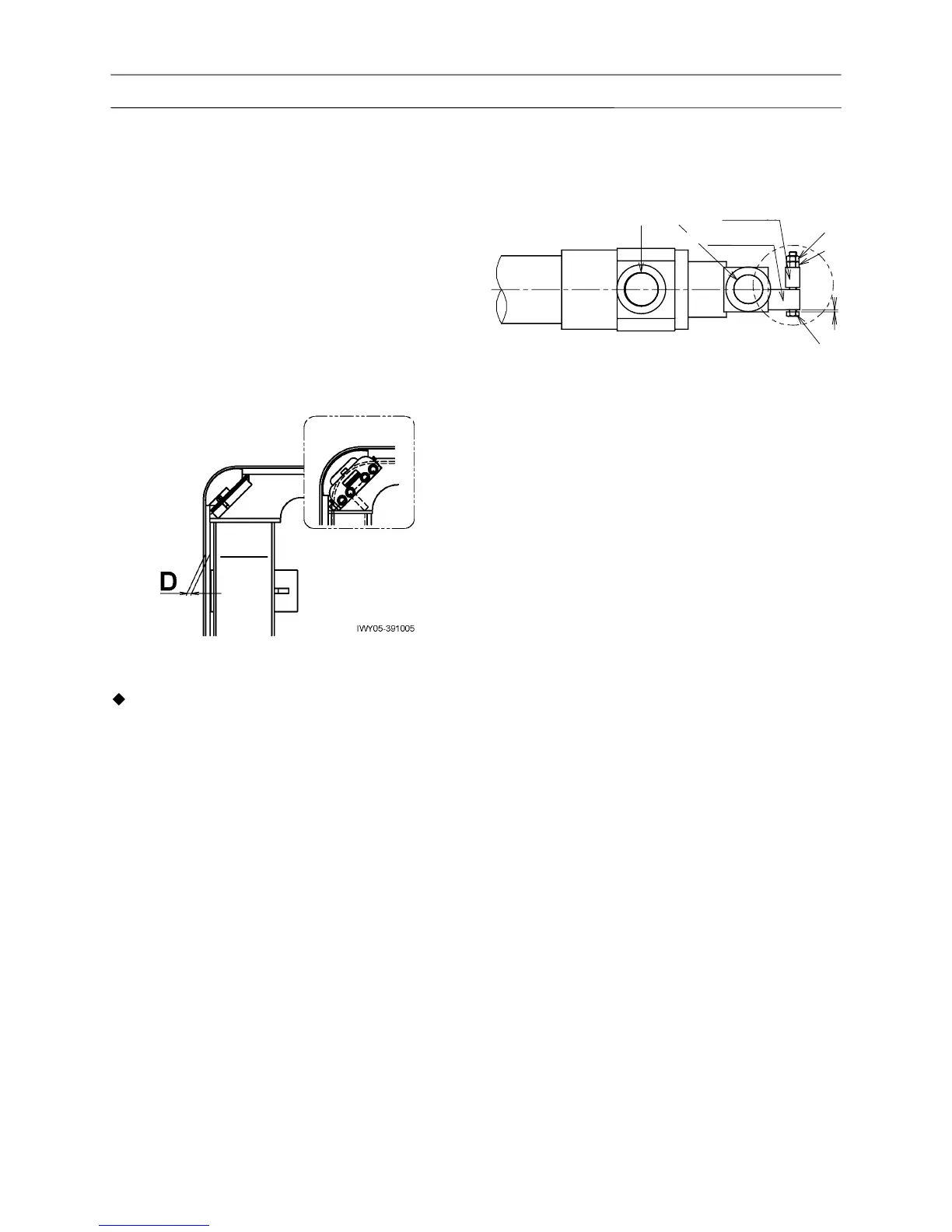
3. Installing and adjusting anti-buckling
bolts for telescoping cylinders
1. Connect the boom and each boom telescoping
cylinder using the pins A and B.
Set the boom horizontal and fully retracted.
2. With the base, 2nd, and 3rd boom sections, adjust
the bolt C locked with the nuts D and E so that it
can be turned by hand and the axial clearance (S)
from the head of the bolt C is 0.5 mm (0.02 in) or
less. (Apply a thread locking agent.)
With the No.3 boom telescoping cylinder on the
left (viewed from rear), its vertical direction differs
from the above figure.