12.2 Front wheel adjustment
• Make adjustments by changing the length of
steering rod (2) so that C = D
+2
0
(mm) is achieved.
• When C > D + 2 (mm) is true, shorten the
steering rod (2).
(A single turn of rod alters the difference
between C and D by approximately 5 mm.)
• When C < D is true, lengthen the steering rod
(2).
• After checking that A = B is achieved (if it is
moved, adjust with steering), confirm that
C = D
+2
0
(mm) is achieved.
• Measure A through H, and record them in the
record sheet.
12.3 Rear wheel adjustment
• Make adjustments by changing the length of
steering rod (3) so that M = N
+1
0
(mm) is achieved.
• When M > N + 1 (mm) is true, lengthen the
steering rod (3).
(A single turn of rod alters the difference
between M and N by approximately 5 mm.)
• When M < N is true, shorten the steering rod
(3).
• Make adjustments by changing the length of
steering rod (4) so that O = P
+1
0
(mm) is achieved.
• When O > P + 1 (mm) is true, lengthen the
steering rod (4).
(A single turn of rod alters the difference
between M and N by approximately 5 mm.)
• When O < P is true, shorten the steering rod
(4).
When an adjustment amount is large, it may
become impossible to turn the rod.
(Because the steering cylinder is locked by the
check valve)
In such cases, operate the rear steering to left and
right once to release the steering cylinder
pressure.
• After operating the rear steering to left and right,
align the lock pin center again, and confirm that M
=N
+1
0
(mm) and O = P
+1
0
(mm) are achieved.
• Measure I through P, and record them in the
record sheet.
12.4 Checking procedure
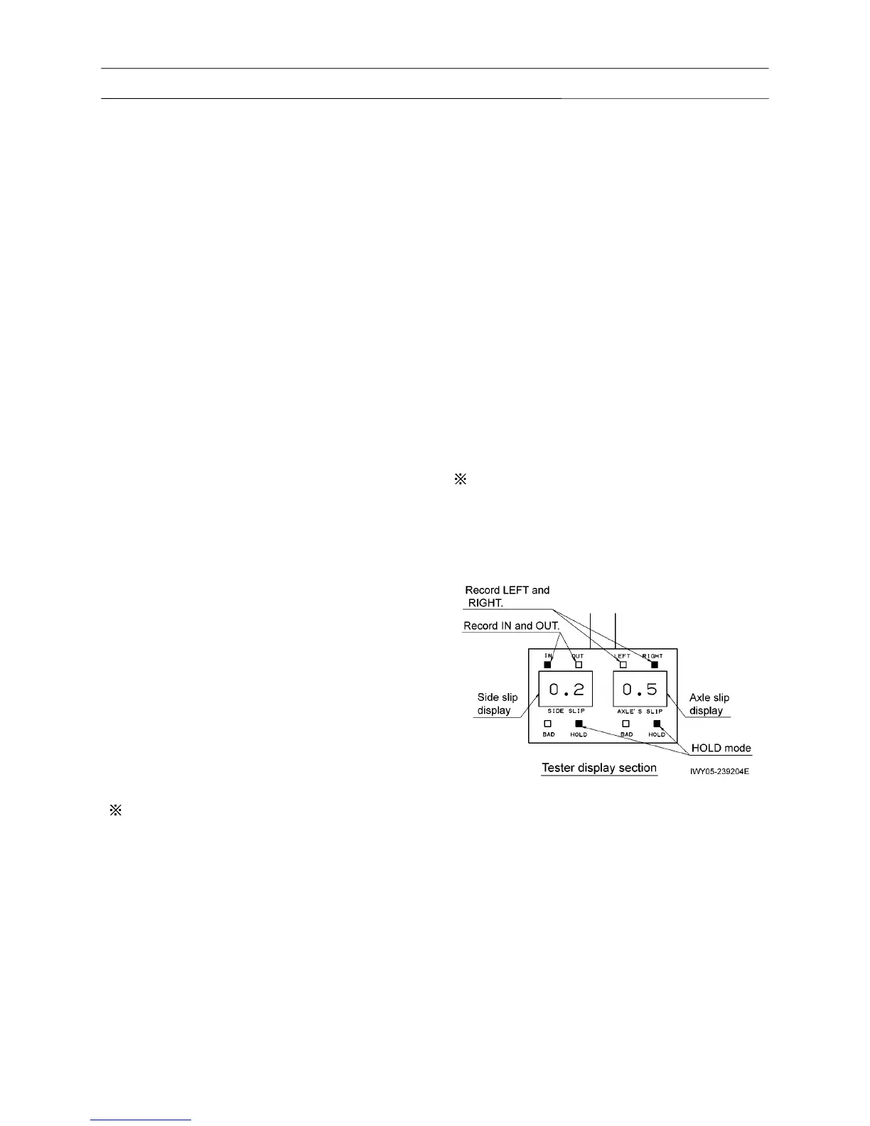
• In the testing ground, measure the side slip and
axle slip.
Tester status:
• "SIDE SLIP" and "AXLE'S SLIP" display status
• HOLD mode
• With the measurement, record the values all
through one axle, and reset the values every time
the measurement of one axle is finished.
• Target value:
• Side slip IN or OUT
Within 3 mm
• Axle slip LEFT or RIGHT
Within 4 mm (1st, 2nd axle)
Within 10 mm (3rd, 4th axle)
If the value deviates from the target value, identify
the wheel status based on the measurement
value, and make adjustments again with an
improved accuracy according to the procedures
described in 12.2 and 12.3.
12.5 After checking
• Tighten the adjustment bolts of steering rods (1)
through (4) to the tightening torque of 76 to 93
N-m (7.75 to 9.5 kgf-m).