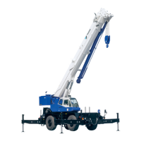
1.11.3 Switch adjustment (front right: CN402, CN403) (rear right: CN406, CN407)
1. Apply a thread locking agent (ThreeBond 1401 or
the equivalent) to the threaded sections of the left
and right switches beforehand.
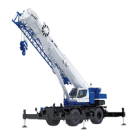
2. Adjusting left switch (CN403, CN406)
Adjust the clearance M between the left switch
detection face and lever (2.5 mm (0.1 in)) so that
the green LED of left switch becomes
extinguished when the support slot and lever hole
A are aligned by the clockwise turning of
adjustment lever. Then, fix by using the nut.
• Nut tightening torque:
19 to 20 N-m {193 to 204 kgf-cm} (14 to 14.8 ft-lbf)
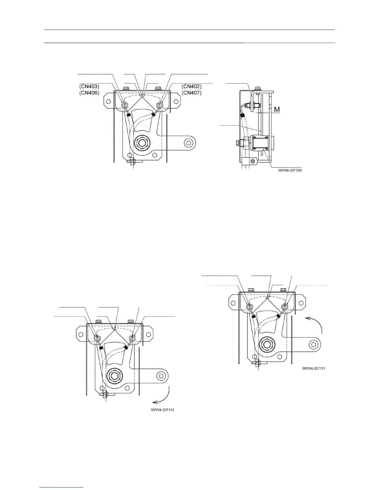
3. Adjusting right switch (CN402, CN407)
Adjust the clearance M between the right switch
detection face and lever (2.5 mm (0.1 in)) so that
the green LED of right switch becomes
extinguished when the support slot and lever hole
C are aligned by the counterclockwise turning of
adjustment lever. Then, fix by using the nut.
• Nut tightening torque:
19 to 20 N-m {193 to 204 kgf-cm} (14 to 14.8 ft-lbf)
4. Align the support slot with the lever hole B, and
check that the LED is lit in green with both the left
switch and right switch.