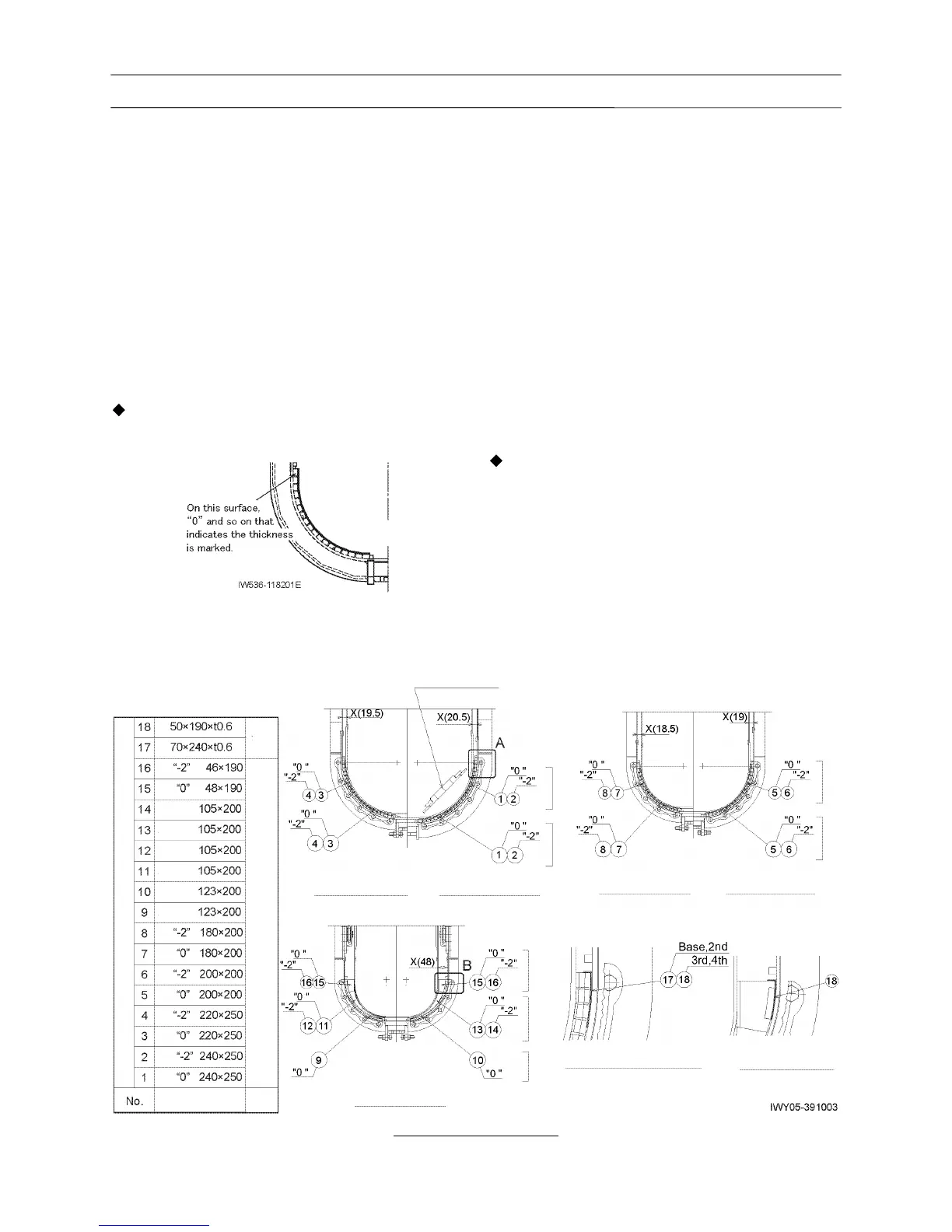
2.4 Slide plate adjustment at lower part
of the boom head
(section [3] indicated in Figure 1)
1. Perform this adjustment with each boom section
retracted almost fully.
2. Before inserting the slide plates, insert the stopper
plate (19).
3. As a rule, use the slide plates of standard
thickness "0".
[NOTICE]
Only when the plates of standard thickness "0"
cannot be inserted, use those of thickness "-2".
4. For the heads of the base, 2nd, 3rd, and 4th boom
sections, select and use the slide plates of the
same thickness for both upper and lower slides for
assembling.
5. For the 5th boom section head, it is allowed to use
the slide plates of different thickness in the upper
and middle parts.
(For the lower part, use the slide plates with
thickness "0" only.)
6. It is allowed to use the slide plates with different
thicknesses between the left and right sides.
[NOTICE]
However, the difference of the clearance between
the boxes (dimension X) shall be 2 mm (0.08 in) or
less between the left and right sides.
7. Insert the shims to the position shown in the figure
so that the horizontal clearance on the upper slide
plates is adjusted to be minimum (0.6 mm (0.024
in) or less). (The total thickness of shims shall be
1.8 mm (0.071 in) or less (0.6 mm (0.024 in) × 3
pieces or less.)
Details of slide plate assy
(Unit: mm) (1 mm = 3.93701×10
-2
in)
Shim