360 354.6
(*1): Wear of sheave groove
5.7 Inspection of the hook block
[NOTICE]
The hook block is an important safety part. Follow
the procedure below to inspect it and be sure to use
it only under safe conditions.
If any problems are found during inspections, repair
or replace the part immediately. A change
inspection must be performed when parts are
replaced.
Inspect the hook block by the instruction of its
manufacture and under the laws and standards of
the country where you use the crane.
1. The sheave groove must be smooth to avoid
damaging the wire rope. Use a grinder to smooth
and correct any sharp corners.
2. Check whether or not the sheaves turn lightly. If a
sheave turns heavily, the wire rope will slide
against the sheave, and the rope may be
damaged. If a sheave turns heavily, inspect the
sheave bearings, and lubricate or replace them if
necessary.
3. Check that the sheave split pins and installation
bolts are securely installed.
4. Check that the hook nuts are securely installed. If
necessary, tighten them further or take steps to
prevent their rotation.
5. Replace any worn or damaged hook nuts
immediately.
6. Check that the wire rope latch functions correctly.
If necessary, replace the spring.
7. Perform a magnetic flaw detection test at least
once a year to check for damage in the hook.
Replace the hook immediately if any cracks are
found.
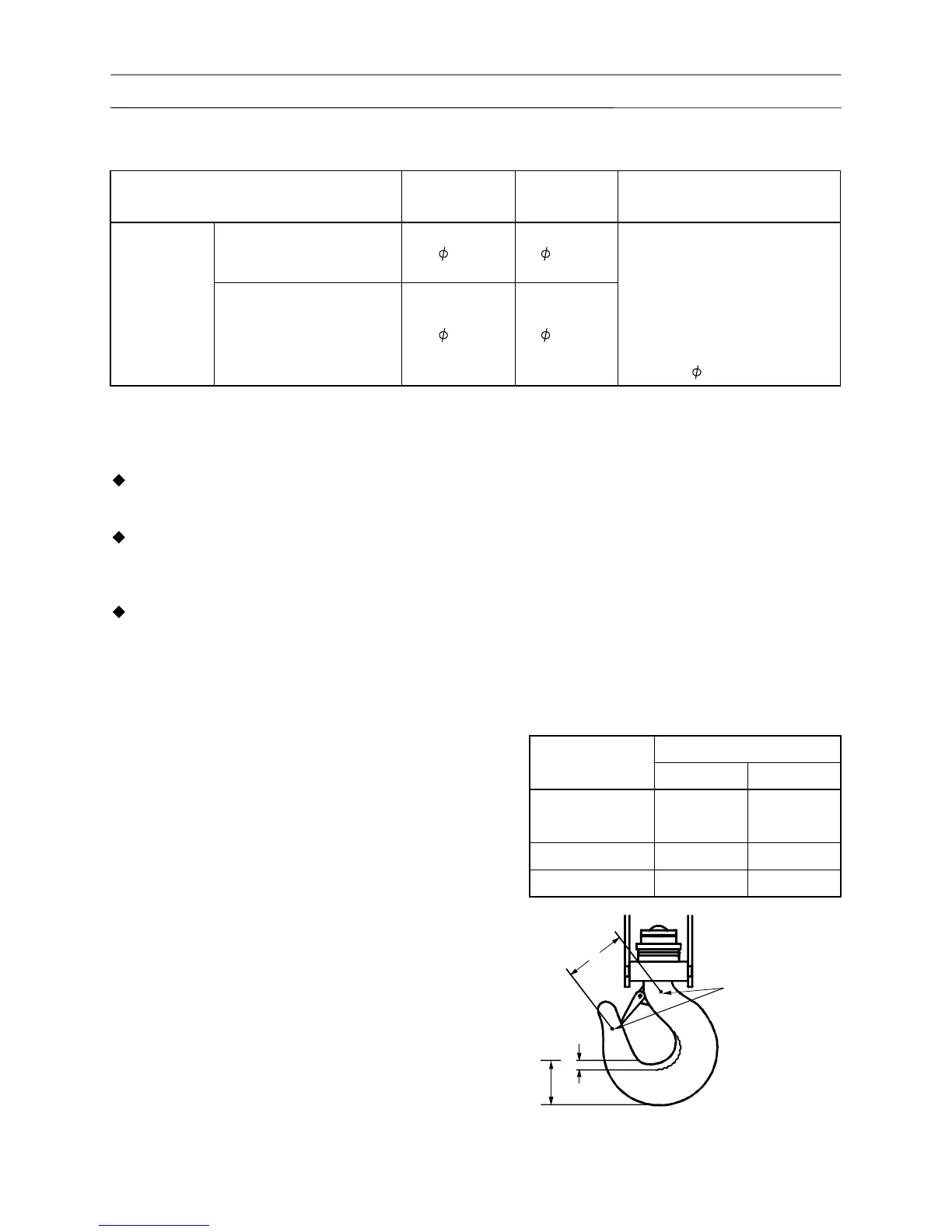
8. As shown in the figure, punch marks are stamped
on each hook. Replace the hook when the
deformation of the dimension (a) between these
marks has increased by 5%.
9. The wear limit of the hook (b) is 3% of the whole
thickness (c).
Hook service limits
(Unit: mm) (1 mm = 3.93701 × 10
-2
in)
Item