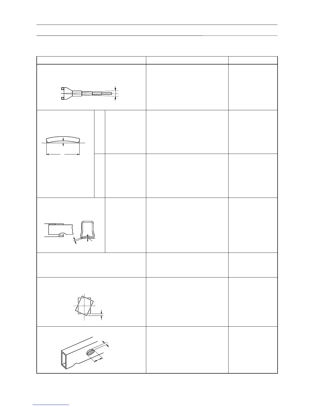
5.3 Boom bending and deformation
(1 mm = 3.93701 × 10
-2
in)
Overall boom bending
(at full extension, maximum elevation angle, with
rated load)
No significant vertical or horizontal
bends shall be found along the entire
boom length.
Set the machine
level.
If necessary, adjust
the clearance
between the boom
and the slide plates
appropriately.
Bend of individual boom
sections
(Lengthwise direction)
Vertical
Base boom section
3rd boom section
4th boom section
5th boom section
B ≤ 14
B ≤ 14
B ≤ 13
B ≤ 13
B ≤ 13
B ≤ 1.5 × L /1000
L: length of each
boom section
Lateral
Base boom section
3rd boom section
4th boom section
5th boom section
C ≤ 9
C ≤ 9
C ≤ 9
C ≤ 9
C ≤ 9
C ≤ 1.0 × L /1000
Indentations at boom overlap
sections
(Bending at boom lower plate)
3rd boom section
4th boom section
5th boom section
Top boom section
In vertical direction
D ≤ 4
D ≤ 3
D ≤ 3
D ≤ 2
D ≤ 2
In vertical direction
D ≤ t/2
Check for deformation of side plates. There must be no large deformation
particularly on the lower half surface
of side plate where pressure
Check for twisting in the lengthwise direction
when boom is fully extended.
E ≤ 5
Check for dents and other localized indentation.
F ≤ 2
(at L
1
≥ 50)
Generally dent G on the 4 corners
cannot be repaired.