-7 Y-7
Assembly Adjustment (Traveling Device)
3. Parking brake adjustment
3.1 Adjusting the clearance
(between brake shoe and drum)
1. Jack up the crane and release the parking brake.
2. Rotate the brake drum. Align the adjustment hole
in the drum with the adjuster wheel for the
lining-drum clearance adjustment.
3. Insert the screwdriver through the adjustment hole
and rotate the adjuster wheel to expand the shoes
until the lining fits the drum (resistance is
encountered).
4. Then return the adjuster wheel by 8 notches. The
clearance between the lining and brake drum is
now adjusted to the standard clearance of 0.23
mm (0.009 in).
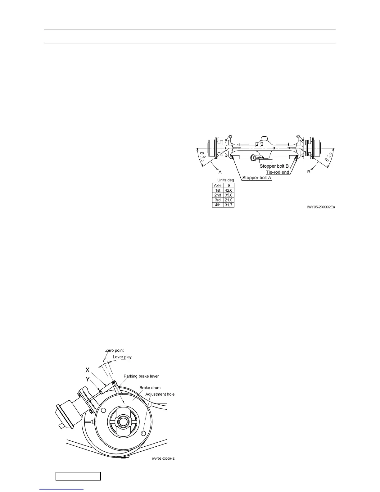
3.2 Connecting parking brake and spring
chamber
1. Place the parking brake lever in the zero-point
position (middle of lever play).
2. While the parking brake is released, the spring
chamber is expanded to its stroke end by the
pressurized air, connect the chamber and brake
lever using material X (end).
3. After connecting, check for any friction between
the drum and lining. Then lock the rod with
material Y (nut).
Lever stroke: approximately 20 mm (0.8 in)
(for reference)
4. Tire and steering angle adjustment
4.1 Tire size and air pressure
• Tire size: 385/95 R25 170E
• Air pressure: 900
+100
0
kPa
{9
+1.0
0
kgf/cm
2
} (130.5
+14.5
0
psi)
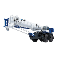
4.2 Adjusting the steering angle
1. Jack up the vehicle and select 8-wheel steering
mode. Turn the steering wheel 2 to 3 times to
bleed the steering cylinders.
2. Before adjusting the steering angle, use a
side-slip tester to check that the amount of tire
side-slip is 3 mm (0.12 in) or less for both the front
and rear tires.
3. If it is more than 3 mm (0.12 in), loosen the bolts
that fasten the left and right tie-rod ends. Then
rotate the tie-rod and adjust the toe-in.
4. Jack up the vehicle on the level surface (so that
the height of the left and right tires is the same).
Use the steering angle measuring jig to adjust the
steering angle in direction A to θ
0
–1
using stopper
bolt A, and the one in direction B to θ
0
–1
using
stopper bolt B.
5. Perform the same adjustment for the wheels on
each axle in the procedure described in the step
4.
6. On only 4th axle, check that the stopper bolts A
and B are not in contact with the housing and the
steering cylinders become stroke end. (The angle
shown in the table above is the reference value of
steering angle at stroke end).
Revised Oct. 2017