57 57
Z-11
IWZ02-617002E
WZ02-6170E
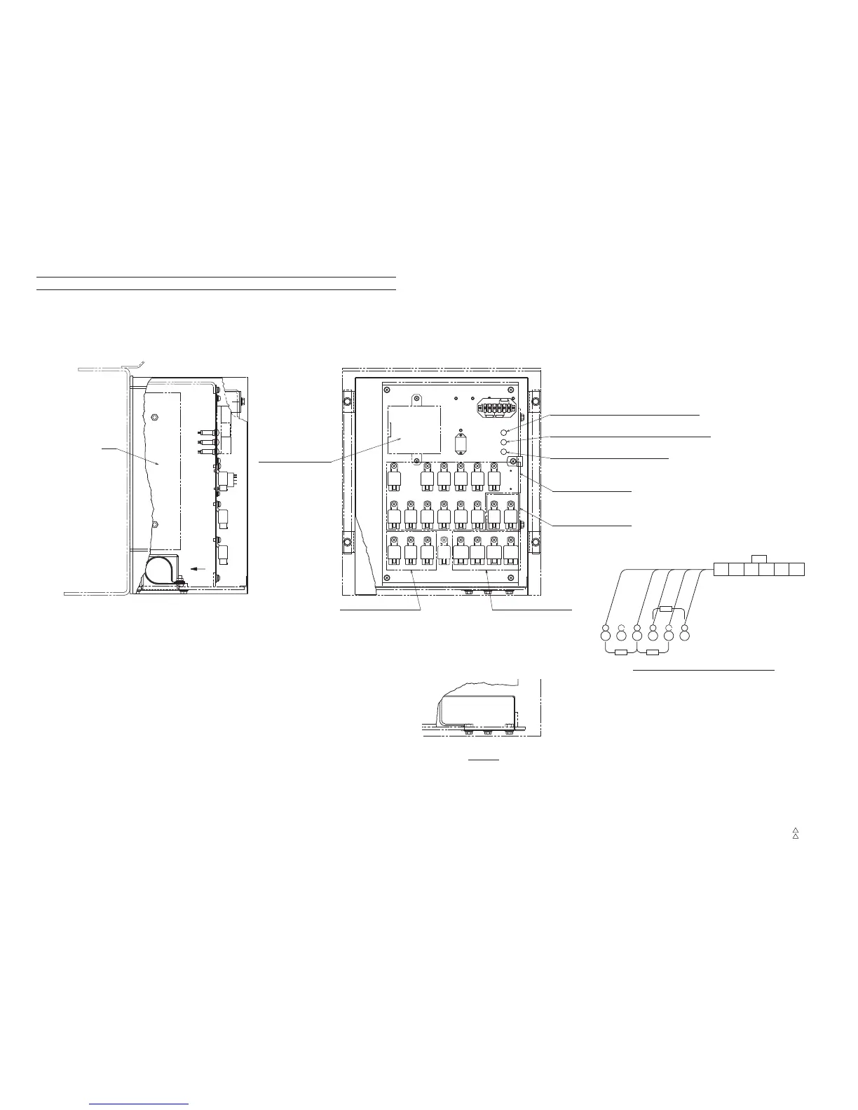
Electric Parts Location Diagram (Lower)
2. Lower electric unit box (VCU, ECU, DIAG LAMP)
Z-11
Z-11
3
349-315-91100
1
349-315-91000
(Retarder accessories)
Spare
Detail of terminal base connection
LED: Orange (Electronic governor: DIAG LAMP2)
LED: Red (Electronic governor: DIAG LAMP1)
LED: Green (Retarder: DIAG LAMP)
c-contact
(Combination type relay)
b-contact
(Normal close type relay)
ECU
a-contact
(Normal open type relay)
b-contact
(Normal close type relay)
VCU
View A
13Ω
91Ω 1kΩ
[1314] B
6 5 4 3 2 1
[115] W/G
[1313] W/R
[136] LG/R
[56] GR
CN765
56
GR
M
115
W/G
1314
B
1313
W/R
136
LG/R
RB3RA75RA27
RA19
RB20
RA96 RB1
RB10 RB14
RA13
RA97 RA98
RF2
RC14RC13RC11
RA16RA15
RA95
RA11
RC12
RA8
A
CN731, CN732
CN733, CN734
CN728, CN729