2 - Names and Functions of Parts
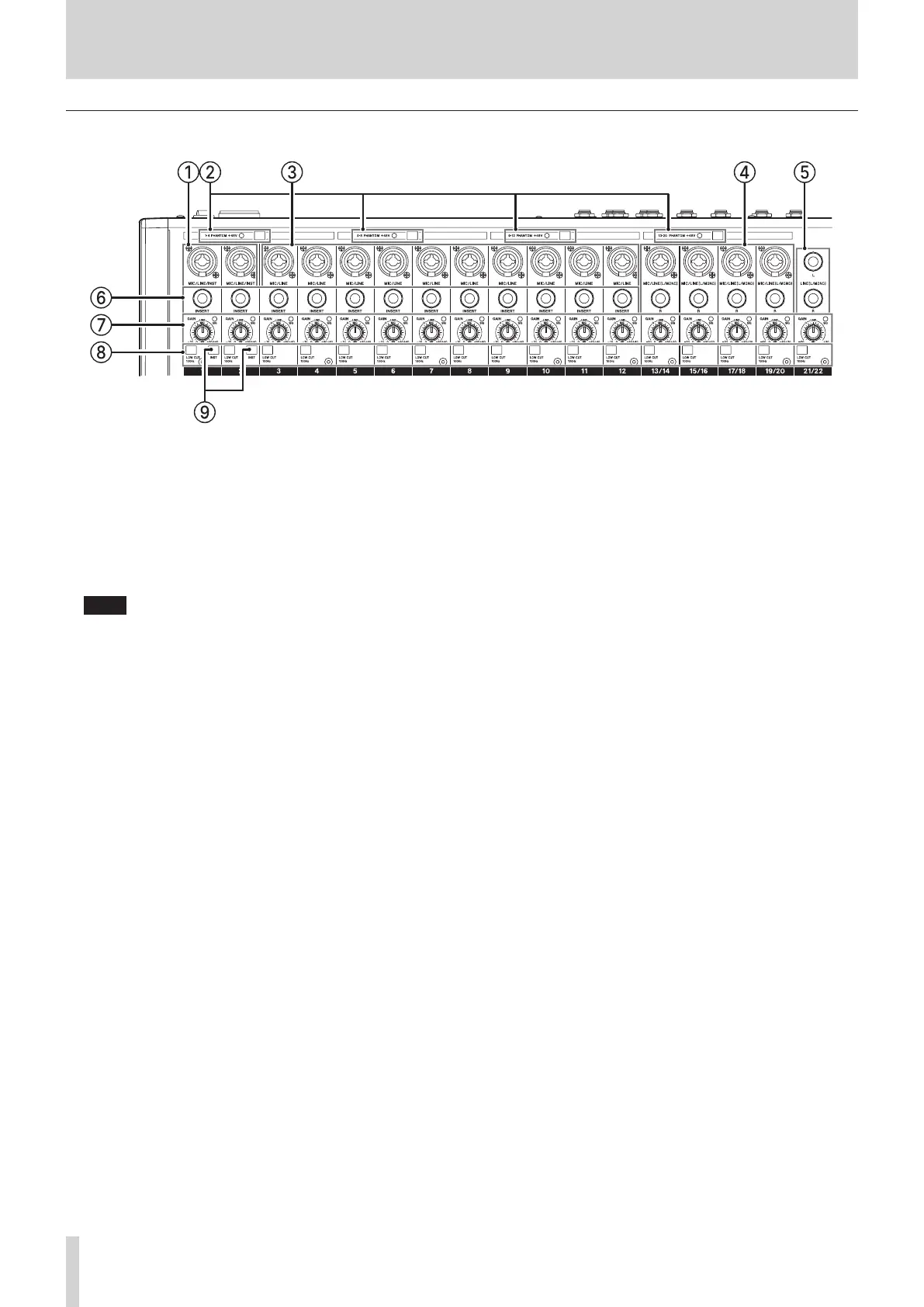
Input channel mixing section-1
1 MIC/LINE/INST input jacks (1–2)
These analog inputs are XLR/TRS combo jacks.
o XLR (1: GND, 2: HOT, 3: COLD)
o TRS (Tip: HOT, Ring: COLD, Sleeve: GND)
The balanced XLR jacks are for XLR balanced mic input.
These standard TRS jacks are for line input.
When directly connecting a guitar, bass or other instrument,
use a TRS jack and turn on (pushed in) the INST switch.
NOTE
When an INST switch is on , input through that MIC/LINE/
INST input jack will be unbalanced.
2 PHANTOM +48V switch and indicator
Use this switch to supply +48V phantom power to the 1–4,
5–8 and 13/14–19/20 MIC input jacks on the top of the unit.
The indicator lights when the PHANTOM +48V switch is set to
on (pushed in). (see "Setting phantom power" on page 29.)
3 MIC/LINE input jacks (3–12)
These analog inputs are XLR/TRS combo jacks.
o XLR (1: GND, 2: HOT, 3: COLD)
o TRS (Tip: HOT, Ring: COLD, Sleeve: GND)
The balanced XLR jacks are for XLR balanced mic input.
These standard TRS jacks are for balanced line input.
4 MIC/LINE (L/MONO) input jacks (13/14–19/20)
These XLR/TRS combo jacks and standard TRS jacks are stereo
analog input jacks.
o XLR (1: GND, 2: HOT, 3: COLD)
o TRS (Tip: HOT, Ring: COLD, Sleeve: GND)
The balanced XLR jacks are for XLR balanced mic input.
These standard TRS jacks are for balanced line input. If only
the L jack is connected, the same signal will be sent to both L
and R channels.
5 LINE (L/MONO) input jacks (21/22)
These standard TRS jacks are stereo line inputs.
If only the L jack is connected, the same signal will be sent to
both L and R channels.
o TRS (Tip: HOT, Ring: COLD, Sleeve: GND)
6 INSERT jacks (1–12, standard)
Use these standard TRS jacks to connect external devices
(eects).
o TRS (Tip: SEND, Ring: RETURN, Sleeve: GND)
7 GAIN knobs and SIG indicators (1–12, 13/14–21/22)
Use the GAIN knobs to adjust the input levels of each
channel.
its SIG indicator will light green when a signal is input (−18
dBu or higher: MIC input).
If a SIG indicator stays lit red continuously, lower the GAIN
knob (+7dBu or higher: MIC input).
8 LOW CUT switches (1–12, 13/14–21/22)
Turn this switch on (pushed in) to enable low cut lters that
cut noise and other sounds at low frequencies.
(Cuto frequency: 100 Hz)
9 INST switches (1–2)
Set these according to the input sources of the MIC/LINE/
INST (1–2) TRS input jacks.
Turn the INST switch on (pushed in) when connecting an
guitar, bass or other equipment with high output impedance.
Turn the INST switch o (not pushed in) when connecting
electronic instruments, audio devices, mics and other
equipment.
8 TASCAM Model 2400