DUT-E installation / Electrical connection / Electrical connection of DUT-E A5/A10/F/I
DUT-E fuel level sensors. Operation manual. Version 8.1
© Technoton, 2020 35
2.7.2 Electrical connection of DUT-E A5/A10/F/I
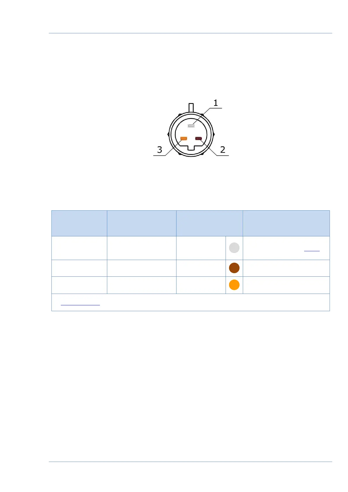
DUT-E A5/A10/F/I electrical connection is made according to pinout of the connector and
interface cable wires description. See figure 19 and table 5 for details.
Figure 19 — DUT-E A5/A10/F/I interface cable connector pinout
Table 5 — DUT-E A5/A10/F/I interface cable wires assignment