DUT-E installation / Electrical connection
DUT-E fuel level sensors. Operation manual. Version 8.1
© Technoton, 2020 32
2.7 Electrical connection
DUT-E is powered from the Vehicle onboard circuit.
IMPORTANT:
1) Before mounting and connecting DUT-E switch off power supply of the vehicle
electrical circuits. To do this switch off the battery switch or release the terminals of
the wires connected to the battery.
2) Prior to electrical connection of the sensor pay special attention to checking Vehicle
chassis ground. Resistance between any point of vehicle chassis and “-” terminal of
the battery or between terminals of the chassis ground switch should not exceed
1 Ohm.
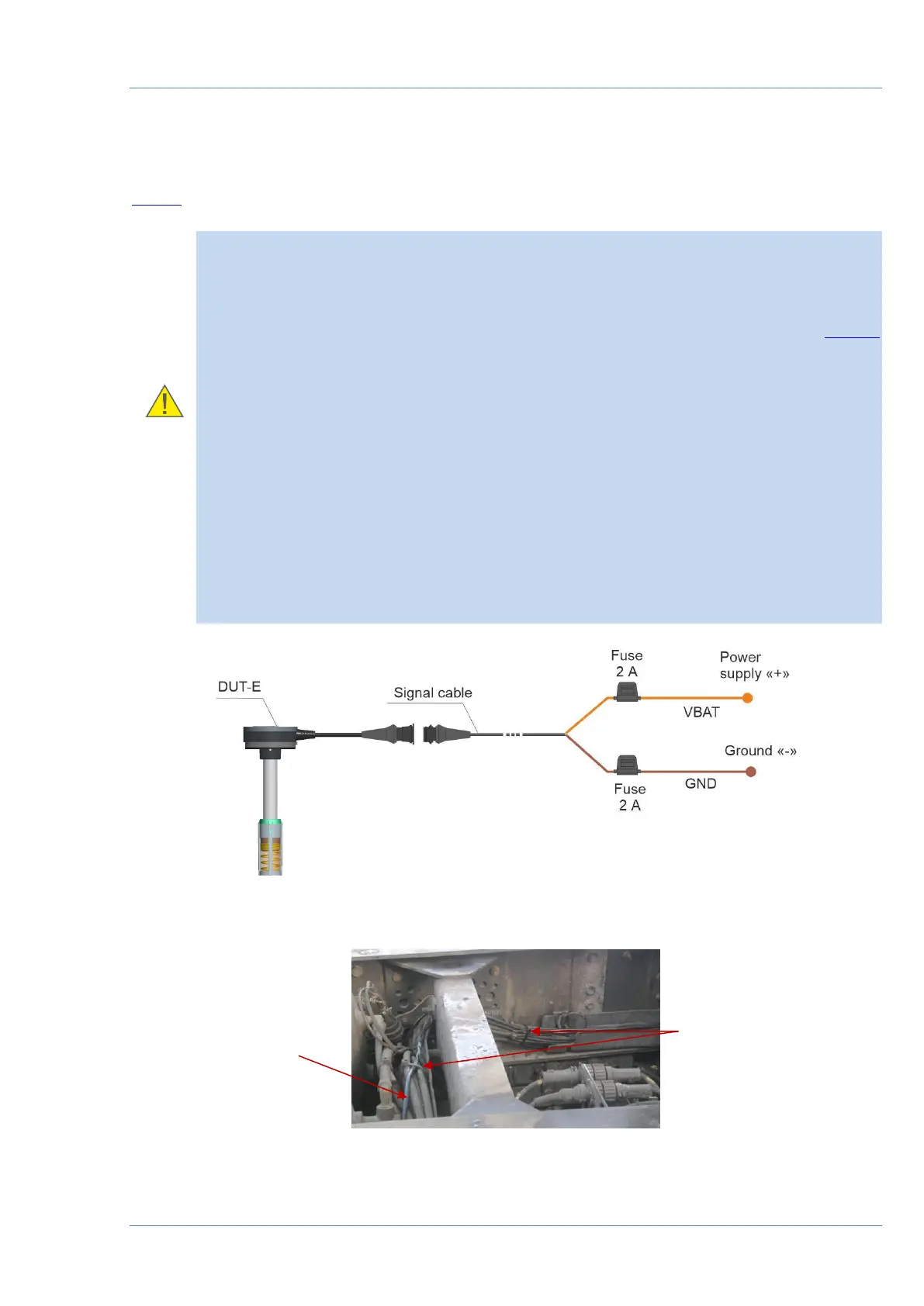
3) When connecting DUT-E to onboard electrical network of Vehicle, use fuses from
delivery set in accordance to scheme of connection (see figure 17 a). Nominal fuse
current is not more than 2 A.
4) DUT-E power supply “+” and Ground “-” wires should be connected to the same
points of vehicle electric circuit as correspondent wires of the tracking device.
5) ) It is strongly recommended to lay signal cable together with standard electrical
vehicle wiring with mandatory cable ties fixing of every 50 cm, at a positive ambient
temperature (see figure 17 b).
6) Quick splice connectors (ordered separately) are recommended for electrical
connection of power supply wires (see figure 17 c).
a) DUT-E to onboard electrical network scheme of connection
b) connection cable laying